Tools needed
Hand tools
- Old toothbrush
- Hand-washing brush (not mandatory)
- A small (roughly about 30mm wide) paintbrush
- Saw for cutting metal
- Tweezers
- Wire cutting plies
- Wire stripping plies
- Wire bending plies
- Tin bending plies
- Tin scissors
- Hammer
- A small cold chisel
- A block from hard wood to support the chiseled part in a vice
- File or something rough to remove burrs
- 7mm wrench, 9mm wrench, two 13mm wrenches
- Screwdrivers suitable for the heads on the bolts you will buy
- A screwdriver suitable for the wire nut
- A sewing needle
Electric and electronic tools
- Calculator
- Electric drill
- Electric drill stand (not mandatory)
- A vice with span of 10cm
- HSS (High Speed Steel) drill bits: 3.1mm, 4.3mm, 5mm, 5.3mm, 6mm, 8mm, 8.3mm
- HSS bits: screw_small_hole, screw_big_hole.
- 10mm masonry drill bit (only for wall holder)
- Soldering iron with grounded tip (may be ungrounded type with additional grounding clip attached during the sensitive operations)
- Multimeter with transistor amplification coefficient measurement (not mandatory)
- Multimeter with DC range 200mV, 2V and 20V and DC range 200uA, 2mA, 20mA (the current measurement is not mandatory)
- A photocell (not mandatory)
Measuring tools
- Ruler
- Slide gauge
- Hard-metal tip stylus or awl or sharpened nail
- Pencil or pen
- Compass
- Ruler
- Saw for cutting metal
- Marker pen for non-porous material with 0...1mm thick trace
Material needed
Electrician
- 4mm^2 wire nut: two-teminal, two-terminal, four-terminal, six-terminal, eight-terminal pieces
- 2.25m of 1.5mm^2 insulated double-conductor cord or something similar
- 1m of 1.5mm^2 insulated single-conductor cord or something similar
- 1m of 1.5mm^2 insulated copper hard wire
- 1m of 4mm^2 insulated hard copper wire
- long length of any two-conductor cord for feeding the lens heating. Used for connecting the wall cube with the optical heads. The conductor gauge is not critical.
Ironmonger's
- Two smoke pipes of nominal diameter smoke_pipe_nominal (actual diameter varies from end to end typically smoke_pipe_diameter+-3mm) and length pipe_length. The pipes are sold usually in 1m pieces and both parts may be cut from one pipe.
- Four smoke pipe caps of nominal diameter smaller than smoke_pipe_nominal, but as close as possible so that they fit into the pipe. We will call it cap_diameter.
- Rough emery paper for grinding off rust
Steelworks
Nuts and bolts and washers
- 5 M3x10 bolts with a flat head (hex, cheese, Philips, Allen)
- 9 M3x15 bolts, galvanized, with a flat head (hexagonal, cheese, Philips, Allen)
- 16 galvanized self-cutting threaded bolts 3.9x>=12mm
- 8 galvanized self-cutting threaded bolts 3.9x>=6mm
- 4 galvanized M4x40 (railing side holder) or M4x60 (remaining holder) bolts with Philips flat head or cheese head or hexagonal head or Allen head
- 8 M4 bolts (smoke_pipe_nominal-shielding_box_width)/2+6mm long with flat head. May be substituted with (smoke_pipe_nominal-shielding_box_width)/2+10mm long pieces of M4 thread bar.
- 6 galvanized M5x30 bolts with hex head or cheese head or Philips head or Allen head
- 8 galvanized M6x90mm bolts in case of wall holder
- Two galvanized M8x70 bolts with hexagonal head or Allen head
- Two galvanized M8x70 bolts with hex or Allen head in case of railing or mast holder or two galvanized M8x90 bolts in case of wall holder
- Eight galvanized M8x160 bolts in case of wall holder.
- Galvanized M8 thread bar. Is sold usually in 1m pieces. You will need 4pieces thickness of railing+80mm long (railing holder) or two pieces thickness of aerial mast+80mm long (mast holder) or none (wall holder)
- 22 M3 nuts
- 36 galvanized M4 nuts
- 8 galvanized M4 washers
- 6 M5 nuts
- 6 M5 washers
- 12 galvanized M8 nuts (railing, wall holder) or 6 galvanized M8 nuts (mast holder).
- Eight plastic 10mm hole plugs (only for wall holder)
Tins
- Two rectangular pieces of a thin tin (0.3mm raw steel, 0.3mm galvanized steel, 0.3mm tin-plated steel, 0.4mm dural, or 0.5mm aluminium) with dimensions 3/4*3.14*cap_outer_diameter+20mm and 80mm+2*cap_outer_diameter. May also be some durable plastic (must be weather-proof when painted) because it will serve only as a hood.
- Tin-plated tin, 0.4mm thick. Two rectangles, 200x180mm and 160x140mm are needed. Copper tin may be substituted, but isn't much strong and is expensive.
Profiles
- Closed square jaeckel profile 30x30x2mm (2x84mm, 2x85mm, 2x100mm, 2x120mm for railing holder or 2x85mm, 2x100mm, mast thickness+60mm, 400mm for mast holder or 2x85mm, 2x100mm for wall holder) for aerial mast holder or 40cm for wall holder). It is recommended to have them cut at the supplier.
- Open square jaeckel U profile 20x20x20x2mm (180mm piece or 320mm piece or 460mm depends on focal_length -- <= 204mm, <=274mm, >274mm). It is recommended to have it cut at the supplier.
- Closed square jaeckel profile 50x50x3mm, for wall holder only. Lengths 2x85mm, 4x150mm, 2x400mm.
Chemistry
- Black matte top coat, water-soluble
- Water soluble primer paint, any colour
- One 310ml cartridge of sillicone sealant (transparent or black opaque, may be both acetic or neutral, without or with fungicide)
- An application gun for the sillicone sealant cartridge
- About 150g of dry sillica gel
Optics
- Two convex glass lenses from loupes of outer diameter lens_diameter (place the gauge over the whole glass piece). Recommended minimum lens_diameter in milimeters is (sqrt(intended distance in metres))*4. Can be bought at cheap market, garage sale or optician's.
- One big retroreflector: white, red, or orange. Can be bought at auto stores.
Electronics
- One 10Mbit/sec. Ethernet Network Interface Card with AUI port or just AUI onboard pinhead (many non-AUI cards have them). It is highly recommended to be a PCI NIC and to be capable of full duplex operation.
- One 12V wall cube (may be unregulated) or 12V A.C. transformer capable of nonstop delivery of 200mA without a risk of home fire (for heating). May be other voltage, but then instead of eight 10-Ohm reistors use eight resistors with value in ohms calculated as source_voltage^2/16.
- Five 4mm cable bushings and two 6mm cable bushings.
- Two 6mm cable bushings and seven 8mm cable bushings (they are numbered according to diameter of cable that can be put into them).
- 0.5m of max. 4mm outer diameter shielded coaxial cable (may be low-frequency)
- Very long piece of double coaxial cable (high-frequency, but low-frequency is also usable up to 20 - 30 meters) or low-frequency shielded double-conductor (shields must be separate). Will be used for connecting the optical heads and the computer - choose the length according to the actual distance.
- 10cm of shielded doublewire (or 2x10cm of shielded cable)
- 1m of shielded four-conductor cable
- Solder
- Colophony
- 250mW Resistors: 7.5 ohm, 8x 10 ohm, 12 ohm, 2x 18 ohm, 22 ohm, 2x 27 ohm, 2x 39 ohm, 3x 47 ohm, 75 ohm, 3x 82 ohm, 2x 100 ohm, 6x 220 ohm, 3x 270 ohm, 330 ohm, 560 ohm, 2x 680 ohm, 3x 820 ohm, 7x 1k, 1.5k, 1.8k, 3x 3.3k, 4x 6.8k, 10k, 15k, 18k, 22k, 27k, 33k, 39k, 47k, 82k, 3x 100k, 2x 120k, 180k, 220k, 2.2M
- Capacitors: 10pF, 47pF, 82pF, 3x100pF, 150pF, 4x1nF, 7x220nF
- Ceramic capacitors: 24x 100nF, 8x10nF
- Electrolytic capacitors: 2x100uF/16V, 470uF/16V
- Diodes: 4x1N4448, 6x 3-ampere rectifier diode
- one schottky diode BAT48 or BAT 46 or BAT 4x
- LEDs: yellow 5mm diffuse, red 5mm diffuse, green 5mm diffuse,
- One transmitter LED: HPWT-BD00 or HPWT-DD00 or HPWT-BH00 or HPWT-DH00 (manufactured by Lumileds)
- SFH203 photodiode (manufactured by Infineon)
- BF988 or BF907 transistor (called MOS tetrode or cascode or dual-gate FET)
- Transistors: 7x 2N3904
- Integrated circuits: 74HC00, 4x 74HC04, 74HC14, 74HC74, 74HC132, LM78805, LM78L05, NE592
- 15pin male CANON connector
- Thermally conductive paste (also called sillicone paste for electronics) (not mandatory).
- Two shielding boxes, at least 70x90mm, but their longer side must fit into the diameter of the pipe with space on each side at least 10mm.
- Duct tapes of various colors
- A very small piece of double-sided blank PCB (Printed Circuit Board)
- Some cable ties (optional)
- 6 EMC/EMI-enhancement ferrite beads or rings or sticks. Can be taken from broken power supplies, monitors and TV sets, or bought at electronics stores. Optional.
Household stuff
- Sheet of paper or old newspaper or magazine suitably large that it can be wrapped around the pipe.
- Detergent
- Water
- Clean dry rag for drying components after washing
- A clean dry rag for wiping the soldering iron
- A piece of old fabric
- A sewing thread
Building
Proceed in building on the following sequence, omitting the unnecessary holders:
- Overview -- do not build anything, just soak in the notion what the whole system looks like
- Fundamentals of manufacturing operations -- read this to prevent fatal mistakes during the building process
- Railing Side Holder
- Railing Top Holder
- Mast Holder (not finished yet)
- Wall Holder (not finished yet)
- Make the pipes and their accessories
- Build the electronics
Testing
If the device has been correctly soldered together, it should work on the first try. But it is possible that you have made a bug somewhere and the testing chapeter is here to help you find it.
I know it is annoying, but now check the topology of all electronics according to the schematics. Be sure all parts are on their place, none is missing, and all joints are reliably soldered together. If in doubt, reheat them to melting point and let them settle down again. If you omit this phase, you have little chance to debug the device without an oscilloscope. If you though have problems, you might ask at the mailing list. Link to the mailing list is accessible from top level of Ronja homepage.
There are several places in the schematics, where the voltages are described. If something goes wrong, try to check them with a multimeter and if they are out of range, either correct them changing the value of part indicated, or find the bug which causes them.
Insert the NIC into your computer and switch it on. Check the voltage on the AUI. If it is bigger than 13V, then insert some 3-Ampere rectifier diodes into the place specified on receiver schematic to keep the voltage down. Insert them in forward direction on the power wire from the AUI. AUIs on PC's have all 12V I think, although the specification permits anything between 12V and 15V, so this is not a real problem. Switch the computer on.
Plug the sole interface into AUI and the yellow light should come up, green light be undefined and stable, and red light not shine. If yellow light is not shining, there is probably some short circuit, so disconnect, measure the power consumption (if 500mA, then there is a short circuit), and find the bug. If red is shining, there is a bug in the logic.
Now plug it off AUI, screw the receiver and transmitter on their short wires into the interface wire nut, and plug it into AUI again. The transmitter should start shining. If not, find the bug. Then align the receiver and transmitter and set up your NIC to full duplex, use arp, ifconfig, route and tcpdump to setup a sniffing loppback test, and put some packets into the device. They should be seen back, with negligible packet loss, and the red and green lights should shine according to the packet density. If this doesn't work, watch the lights and try to debug the device (cold joint, bad topology, missing part).
Now "tune" the transmitter to 50% duty cycle wave. It is optional, but enhances the performance. Place a photocell over the transmitter and measure the DC current when no packets are going and when many long packets are going (the red light on interface is shining vigorously). The values will somewhat differ (probably) and you have to manipulate the value of the resistor that is between pins 14 and 1 of the triple chip in the transmitter. Increasing the value will give less light during the packets.
Now take a mirror and try to reflect the beam on as big distance as possible. It should be able to make something around one meter of total path length (say 70cm to 140cm). If it is suspiciously short, then the receiver is botched. Find the bug and if there is none, then there is a cold joint somewhere - reheat the joints again. If it doesn't help, do the same with the transmitter. Last chance is there is something bad in the interface near the wires that go to receiver and transmitter. If you can not find the bug, try to measure various values with a multimeter, and last instance is the mailing list of course or borrowing an oscilloscope.
Installing and aiming
Screw on the holders as necessary. Then put the pipes (optical heads) onto them and tighten. Connect the wires together on the wire nut inside the pipe cap, both on receiver and transmitter. Ask the other side of the link to install a retroreflector near their receiver (or on it) and to switch off the transmitter.
Connect the heating pair in your home to the suitable 12VDC wall cube and leave it on unless there is low humidity out there.
Now put one bag of sillica gel into each pipe (beside the box with electronics, behind the thermal shield) and close the cap and screw it down with the screws.
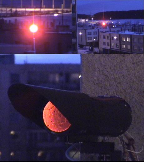 |
The picture shows what the transmitter beam looks like from 260m
distance (130mm diameter transmitter lens) and the big image is the
90mm transmitter in operation from close, out-of-axis view.
Now wait until dark (or at least twilight) and aim the transmitter onto some distant house. Loosen the focus (with #7 wrench) and focus until you see a bright spot. Then tighten. Move the transmitter onto the retroreflector and play with both M8 bolts (two #13 wrenches) and the focus until you get maximum brightness on the retroreflector. Then carefully tighten and watch the spot to be sure you have not drifted during tightening. Measure the received signal strength shortly before you leave the roof and write it down and put it into a safe place for future reference to be able to say if something went wrong. Ask the other party to aim their transmitter. Then connect the DC voltmeter on 200mV range to the measuring port of the receiver. Then put the focus of the receiver into middle position and fuss around with the receiver until you see some numbers on the meter. Now play with the focus and aiming until you get maximum count. Now freeze down the setting by tightening the nuts down, again watch the meter not to decrease the count (which would mean corrupting the optimum aiming). |
Now set up your IP network and do some pings, FTP's, ssh's, and so on, to be sure that it works flawlessly. Then climb to the roof again and seal all seams on the tube with the sillicone sealant to be sure no humidity or water will leak inside.
Maintenance and troubleshooting
It is possible that the lenses will become dirty from the outer side. You may either spray them with a water with a drop of detergent (Ronja will be defunct for some short time after it because it will not see anything) or wipe them with some soft rag and be careful not to scratch the surface. Nevertheless, they must be really dirty for the signal loss to be observable as excessive packet loss.
Maybe the sillica gel will eventually become saturated from the trace humidity that leaks inside no matter how it is sealed. Then tear off the sealant around the cap, unmount the cap, remove the bags, put the into oven for half an hour until they are absolutely dry, and replace them, replace the cap and seal it again with the sealant.
All electrical contacts are made from wire nuts. If the device suddenly stops working after a long period of troublefree operation, this is probably the case. The oxidization together with temperature changes brought eventually two layers of copper oxide against them and prevented the contact. Loosen all wire nuts in the device and retighten them again. This will cut brand new touch surfaces and ensure reliable contact again.
If it stops working, check visually if there is a signal from the other side, and if there is, check the alignment with a meter. If the receiver is dead, then there was probably a cold joint that became a no-joint over the period of time undr the influence of temperature changes. Resolder the box thoroughly and neatly. Do the same if the transmitter stops to transmit light (first check the diode if it is not burnt out).
The LED has lifetime up to 100,000 hours, which is 12 years of 24/7 operation. The light output very slowly decreases over time. If you think it is shining too dimly, then replace the diode with another one. The diode is ran exactly at recommended maximum current. The LED lifetime is being exhausted when the device is powered - no matter if data go through or do not. Also the LED shines 50% more at -20 degC than at 40degC. This is somehow a compensation for the bad weather during winter and good visibilities during summer.
Epilogue
I congratulate you to the decision of building Ronja 10M Metropolis. I wish you a clean success and many years of reliable, uninterrupted operation.
Enjoy the Megabits.
(c)2001 Karel 'Clock' Kulhavy, e-mail address: clock at atrey dot karlin dot mff dot cuni dot cz