|
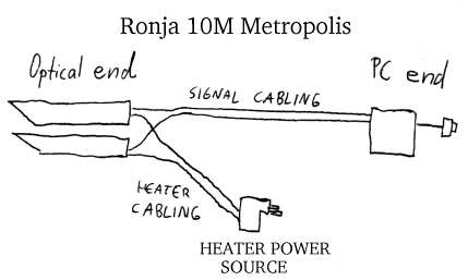
| Ronja consists of PC end, signal cabling, heating cabling, heating power source, optical end. |
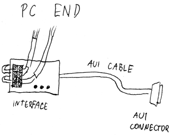
| PC end consists of interface, AUI cable, AUI connector. PC end is near the PC. The distance may be in order of tens of meters. |
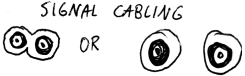
| Signal cabling consists of one or two cables. Sinal cabling connects PC end
to optical end. Signal cabling may have optional ferrites on each end.
The signal cabling is two coaxial cables (high frequency) or shielded 1-conductors (low frequency), or a single, shielded 2-conductor (with two separate shields, low-freqeuncy) where the shield must be made of copper (to be solderable). The maximum recommended length for low-frequency cables is 25m, the maximum recommended length for high-frequency cables is 50m. One shield is ground and the other +12V feeding the optical end's electronics. The signals are 700mVpp square waves. The receiver signal is compatible with the transmitter signal after shield decoupling. The signals bear no DC information. A positive excursion means light, negative darkness. There is the 1MHz square wave already mixed between the packets here. The function is to carry the signals to and fro and to feed the optical end's electronics with power. Lay the cables together or via separate routes, don't bend them over edges. The cables may be laid next to power lines. |
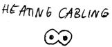
| Heating cabling consists of a long cord. Heating cabling
connects heating power source to optical end.
The length is unlimited, the gauge of the conductors is not important. The voltage is 12V DC or AC nominal, but may be different if the heating resistors' value is recomputed to voltage^2/16. The function is only to provide heating power. It is not necessary to heat when there is nice weather out there. Do anything you want with the cable, nothing matters. |
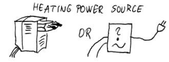
| Heating power source is a wall cube or transformer.
It's DC or AC voltage is 12V nominal, but not important as long as the
heating resistors are accomodated to the voltage - the resistance in ohms
must be volts^2/16.
The function is to provide power to the heating power without a risk of fire. Install the wall cube or transformer anywhere you want where you can conveniently plug it off when bad weater ends. |
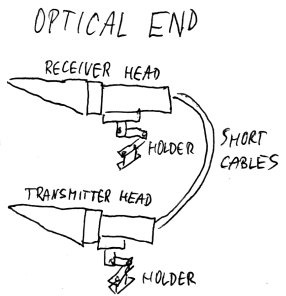
| Optical end consists of receiver optical head, transmitter optical
head, their holders, and short cables interconnecting the heads togeter.
The optical end takes 12V, one signal, produces another signal, receives optical information, generates optical information. Install the optical end on your balcony, roof or anywhere where is the required visibility, and don't route the light beam just above hot roofs or near hot walls to prevent distortion of the reception. Also be sure any horizontal surfaces under the lenses are enough far away so that rain falling on them will not splash on the lenses. |
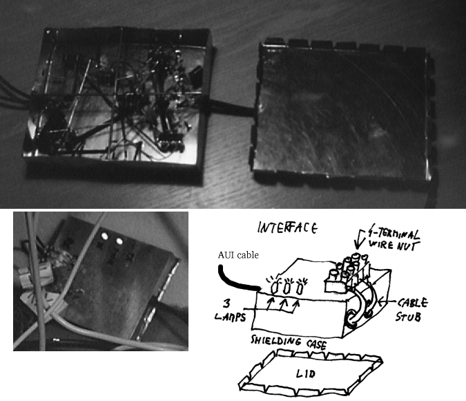
| Interface consists of shielding case, shielding case lid, 4-terminal
wire nut mounted on the case, and cable stub. There are 3 lamps on the
case. The cables go through cable bushings.
The interface contains lots of electronics parts soldered directly into the shielding case. The lid is for shielding purpose. The interface translates the occasional AUI signals into the continous carrier wave for the optical route. It also indicates receiving and transmitting packet and presence of power. The +12V power from AUI goes through it to signal cables. The interface also consumes a part of it. Install the interface there where you will see the LED lights. |
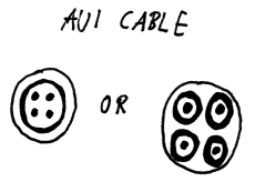
| AUI cable is max. 1m long shielded four-conductor cord. Connects interface
with AUI connector.
There are asymetrical (TX) and symetrical (RX) AUI signals going over the cables with AUI-specified levels. The cable goes through cable bushing on one end where it is stripped and soldered inside the interface. On the other side, it goes into the AUI connector where it is tightened down with a clamp to prevent tearing off. |
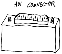 |
AUI connector is a 15-pin CANON male. It is to be plugged into AUI of the network card on the PC. There is one 39R resistor inside and many pins are connected to the shell. |
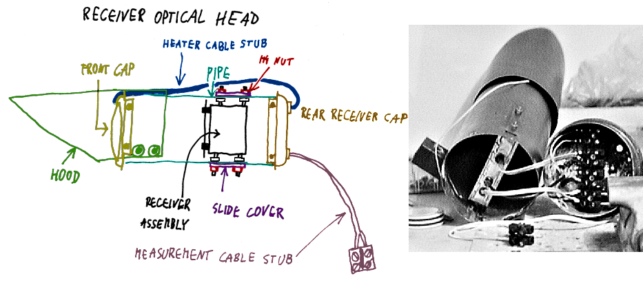 | Receiver optical head consists
of hood, front cap, pipe, receiver rear cap, receiver assembly, 2 slide
covers, heater cable stub, and measurement cable stub. The hood is screwed
to the pipe using 4 self-cutting screws and 4 washers. Front cap is
screwed to the pipe using 4 self-cutting screws. Rear cap is screwed to
the pipe using 4 self-cutting screws. Receiver assembly has four M4 bolts
that are going through slots on the pipe, are covered with slide covers
and tightened with 4 M4 nuts. The heater cable stub connects the rear
receiver cap with the front cap, going on the outer side of the pipe. The
measurement cable stub dangles from the receiver rear cap and is
terminated in two-terminal wire nut. The head receives optical signal from infinity, focuses it onto the detector of the receiver and puts the resulting signal into the signal cable. |
|
Transmitter optical head consists of hood, front cap, pipe, transmitter rear
cap, transmitter assembly, 2 slide covers, and heater cable stub. The hood is
screwed to the pipe using 4 self-cutting screws and 4 washers. Front cap is
screwed to the pipe using 4 self-cutting screws. Rear transmitter cap is
screwed to the pipe using 4 self-cutting screws. Transmitter assembly has 4
M4 bolts that are going through slots on the pipe, are covered with slide
covers and tightened with 4 M4 nuts. The heater cable stub connects the rear
transmitter cap with the front cap, going on the outer side of the pipe.
The head focuses the LED diode into infinity and thus casts the light just on the receiver on the other side of the link. |
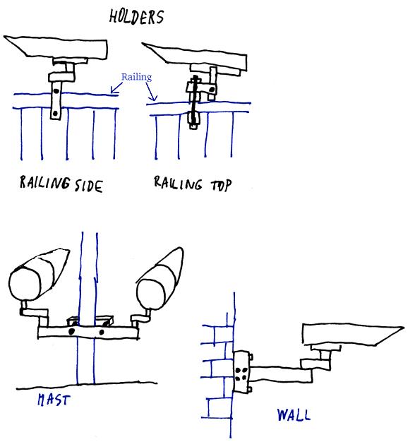 | There are 4 types of
holders: railing side, railing top, mast, and wall. The holders are
separate for each head (railing or wall), or common (mast). The heel of
the holder touches the pipe of the optical head and they are screwed
together using M5 screws. The holders allow precise and stable adjusting of direction of the optical heads. They also provide enogh stability during heavy wind so that the beam doesn't get misaligned. |
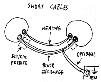 |
Short cables interconnecting the two optical heads are those: short heating
cable (insulated one-conductor cord) and short power exchange cable (marked as
CON_12V and CON_GND in the schematics, insulated two-conductor cord). There may
be optional EMI/EMC enhancement ferrites on each end of the power exchange
cable. The CON_GND of the power exchange cable may be tapped and connected to
the earth common for safety.
The power cable shares +12V and ground between the both heads, the heating cable shares the heating power between them. The cables are just hanging between the heads. |
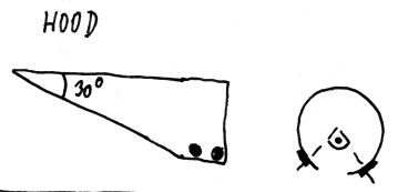 | The hood is a smooth shape
cut from thin tin, bent around the pipe. The hood covers approx. 3/4 of
the pipe's circumference. The heating cable stub goes under the hood.
The hood protects the lenses from rain, especially during windy rainstorm. |
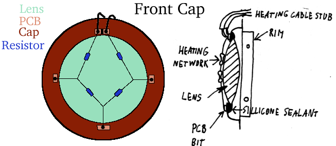 | Front cap consists of
smoke pipe cap, glass lens, and heating network. There is a circular hole
in the cap, in which the lens is held by silicone sealant. The heating
network is soldered on 4 tiny PCB (Printed Circuit Board) pieces on the
edge of this hole from the outer side. There are two terminals on the
network which are served by heating cable stub. The network comprises 4
resistors in series lying on outer surface of the glass lens. There are 4
holes regularly placed on the rim of the cap for self-cutting screws.
The heating network prevents condensation of moisture on the lens during moist weather. The purpose of the cap is to permanently hold the lens in place. |
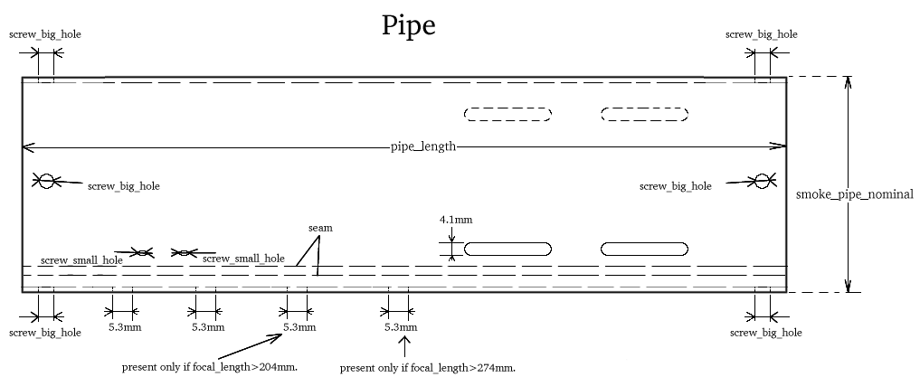 | The pipe is a piece of standard smoke pipe or rain gutter pipe (thin tin). Thick tin or steel pipe is not allowed due to need to deform the pipe to insert the receiver/transmitter assembly. The pipe has 4 holes for holding of front cap, 4 holes for holding of rear cap, 4 holes for holding the hood, 4 M4 slider holes for holding receiver or transmitter assembly, and 2-4 M5 holes for attaching the holder's heel. |
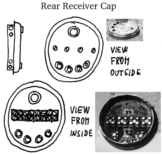 | The rear receiver cap consists of smoke pipe cap, and 8-terminal wire nut. There are 4 M3 holes for holding the wire nut (using 4 M3 bolts and 4 M3 nuts). There are 4 holes for self-cutting screws regularly spaced on the rim for attachment to the pipe. There are 4 10mm holes with 8mm cable bushings under the nut and one 8mm hole with 6mm cable bushing above the nut. The bushings are attached with sillicone sealant from boths sides. |
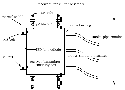 |
The receiver/transmitter assembly consists of receiver shielding case with
lid and electronics inside, thermal shield, and 4 M4 bolts protruding from
sides of the case. The thermal shield is a byproduct of cutting out the big
holes from front cap. There is a PIN/LED diode hole on the front and two
(transmitter) or three (receiver) holes with cable bushings and cable on the
rear. The shield is attached using 2 M3x10 bolts and 6 M3 nuts. The M4 bolts
are secured using 4 M4 nuts, and additional 8 M4 nuts form placeholders that
fit the inner diameter of the pipe.
The thermal shield shields the detector from spurious sunlight, shields the electronics from the heat of sun concentrated through the lens, and improves electrical shielding of the photodiode. |
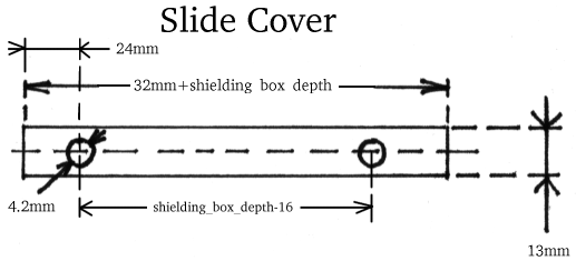 | The slide covers are short stripes of tin with two M4 holes that cover the sliding holes agains rain and make the assembly more rigid. |
| The transmitter rear cap consists of smoke pipe cap, and 6-terminal wire nut. There are 3 M3 holes for holding the wire nut (using 3 M3 bolts and 3 M3 nuts). There are 4 holes for self-cutting screws regularly spaced on the rim for attachment to the pipe. There are 3 10mm holes with 8mm cable bushings under the nut and one 8mm hole with 6mm cable bushing above the nut. The bushings are attached with sillicone sealant from both sides. |
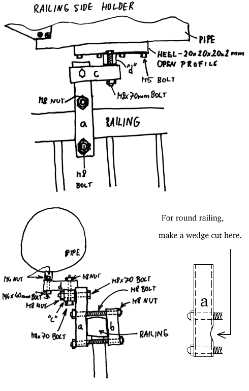
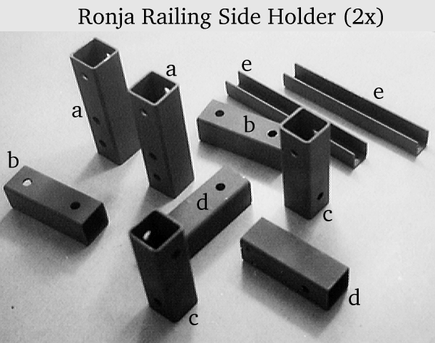 | The railing side holder consists of 4 closed square steel profiles (a,b,c,d), 1 open square steel profile (heel, e), two M8x70 bolts, two long M8 bolts, and 6 M8 nuts. The closed steel profiles are 30x30x2mm and contain M8 or M4 holes. The open profile if 20x20x20x2mm, contains M4 and M5 holes and is to be mounted to pipe of optical head by 2-4 M5 bolts. The heel is attached to open profile using 2 M4x40 bolts and 2 M4 nuts. The long M8 bolts are sized according to railing dimensions. The M8x70 bolts serve as axes of independent movement. |
 |
The railing top holder is the same as railing side, except for M4x60 instead of M4x40, and different placement of holes on the profiles.
The mast holder serves both optical heads at once. Consists of 6 closed and 2 open square steel profiles, 4 M8x70 bolts, 2 long M8 bolts, 8 M8 nuts, 4 M4x60 bolts and 4 M4 nuts. The closed profile is 30x30x2mm and contains M8 or M4 holes. The closed one is 20x20x20x2mm, contains M4 and M5 holes and is to be mounted to pipe of optical head by 2-4 M5 bolts. The long M8 bolts are sized according to mast diameter. The M8x70 bolts serve as axes of independent movement.
The wall holder consists of 3 50x50x3 closed square steel profiles, 2 30x30x2 closed square steel profiles, 1 20x20x20x2 open square steel profile, 4 M8x160 bolts, 2 M8x70 bolts, 4 M6 bolts, 2 M4x60 bolts, 6 M8 nuts, 2 M4 nuts. There are M8 holes in the big closed profiles, M8 and M4 in small closed profiles, M4 and M5 in open profile. The open profile is a heel and is to be flushed with the pipe of the optical head and tightened with 2-4 M5 screws. The M8x70 bolts serve as axes of independent movement.
The EMI (ElectroMagnetic Interference)/EMC (ElectroMagnetic Compatibility) enhancement ferrites are rings (on which several turns of the cable are wound), beads (throught which the cable goes), or rods (several turns, plus secured with duct tape) put on the cable and fastened using a duct tape. They prevent spurious longitudal waves from spreading all over the cabling and radiating out. They are the same that can be seen on PC monitor signal cables.
All electronics is soldered directly into the metallic cases without use of PCB and is held together by the natural rigidity of the parts.
All metallic parts are painted with two layers of black matte water-soluble paint including from inside. Parts that may corrode have additional two layers of anti-corrosive water-soluble primer underneath.
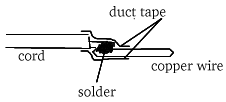 | All cables are connected together using the following method: there is a 20mm long piece of 4mm^2 hard copper wire soldered to the end of the conductor, the joint is insulated and the wire is plugged into wire nut, where it is tightened hard down. |