Efforts in
developing upward and
directional thrust
by
Stavros G. Dimitriou
TEI - Athens, Dept. of Electronics
E-mail: dimsta@ee.teiath.gr
,dimsta42@hotmail.com
A
presentation
provided for
the Propellantless Propulsion Conference
January 20-22 2001
at the University of Sussex
Abstract
Two experiments are presented below, regarding the production of upward lift and directional thrust respectively. The upward lift is created due to the presence of high-intensity currents present on the shorted rim of a lamda /4 transmission line and is demonstrated as a shift in the center of weight of a horizontally suspended transmission line. The directional thrust is developed on a pair of thin-dielectric plane capacitors and is demonstrated as a torque force, acting on the mass of their metal plates. The two capacitors are connected in anti-phase and driven by a slope-asymmetric waveform. They are attached at the ends of a wooden beam, suspended horizontally from an inverted -V thread.
INTRODUCTION
This demonstration is based on some theoretical concepts developed in the M.Sc thesis "Radiation Phenomena of Specially Shaped Current Pulses" (University of Manchester, 1994, by the author. This work is currently displayed on the web thanks to Jean-Louis-Naudin, to whom the author is grateful. The basic equations pertaining to coupling from the EM domain to the mechanical one are reproduced here for convenience.
From the expression of the electric field in space,
![]() (1)
(1)
By taking the partial derivatives,
![]() (2)
(2)
From (1), (2), :
![]() (3)
(3)
From (3), :
![]() (4)
(4)
Differentiating (4),
assuming changes slow enough so that the static formula for the
electric field can still be applied in practice with satisfactory
accuracy:![]()
![]() (5)
(5)
![]() (6)
(6)
It can be shown that in a plane capacitor,
![]() (7)
(7)
![]() (8)
(8)
THE PROPOSED
PRINCIPLE FOR
THE PRODUCTION OF UPWARD THRUST
In producing upward thrust, use is made of equation (5) above. Currents are created in a resonant structure, parallel to the surface of the Earth. Their presence, due to eq.(5), is equivalent to a state of velocity. By doing so, every part of the structure carrying this current is in an equivalent state of velocity tangent to Earth and should therefore be subjected to a centrifugal force
![]() (9)
(9)
where:
![]() is the mass of the conductor
carrying the current (to take into account the skin and proximity
effect, per case, regarding alternating current).
is the mass of the conductor
carrying the current (to take into account the skin and proximity
effect, per case, regarding alternating current).
R is the Earth radius and
h is the height of the structure from the surface of the Earth. Evidently h can be omitted for any practical purpose, as h<<R.
Q is the quality of the resonant structure used.
It follows that it is of great advantage the use of high-surface, high Q resonators. These can be in the form of flat transmission lines or pancake cavities, suitably excited, to retain the highest Q possible.In this way, a very efficient lift can be created. The resonators ca generally be made circular or form only a circular sector. In the second case, several resonators could be excited separately, thus giving a craft the capability to have different values of lift per sector.
The RF energy is mostly contained within such a structure, thereby reducing the problem of EM interference and/or exposure.
The devices built so far all suffer from low Q values and therefore the upward lift force has not been measured witth sufficient accuracy.
THE EXPERIMENTAL DEVICE OF UPWARD LIFT.
In attempting to measure the lift of a circular transmission line made of ordinary printed circuit board (having epoxy or bakelite as a dielectric), the losses of the dielectric mass hinds the possibility of obtaining a sizeable amount of lift, detectable by a simple non-metallic balance, to eliminate any possibility of interaction of the phenomenon with the metal parts of the balance. The use of electronic balances is usually prone to RF interference from the experiments and may lead to ambiguous results.
To overcome these facts, a different approach has been adopted:
A circular sector is used, It occupies 30 degrees of arc and has a radius of 85 cm. It is made of epoxy PCB material with a dielectric constant of 5.2, approximately. This device is hung horizontally from its center of weight and excited by an attached VHF oscillator. Upon excitation, the high current area of this transmission line, close to its short-circuited rim, is subjected to a lift force, as stated above. In this way, the balance of the device is violated, because its center of gravity is shifted. This is easily detected optically and serves as a qualitative indication of the described phenomenon. For a quantitative replication of the experiment, any benevolent offer of replication and/or upgrade is thankfully welcome.
The circular sector transmission line and the relevant oscillator circuit are shown in the end of this document, at Figures 1 and 2 respectively.
PRODUCTION OF DIRECTIONAL THRUST.
For the production of directional thrust, use is made of the equations (6) and (8) . Equation (6) is used to provide thust from a current in a conductor. In the present demonstration, advantage is taken of the current flowing in a capacitor, as described in equation (8).
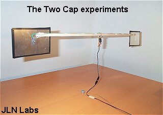
The capacitor used in this case is a twin thin one, made of two thin plates of copper 0.1 mm nominally), having a double-sided self-adhesive tape as a dielectric, of thickness 0.35mm.. The dimensions of this structure are 9.3 by 14.7 cm/ Two rectangular plane capacitors are used with their centers of the rectangles placed 57.4 cm apart, by a lightweight wooden beam.
These two capacitors are excited in opposite polarity by a small 555 oscillator, producing a waveform with an exponential rise and a ramp fall part. This waveform has a net derivative of current different than zero per cycle. A force is thus produced on each capacitor. As the two capacitors are driven in anti-phase, they produce a torque which revolves the whole apparatus by a readily observable angle. The direction of rotation can be reversed by reversing the polarity of the waveform applied to the capacitors, To do so, an inverting DPDT switch is incorporated in the circuit.
The capacitor arrangement, the relevant circuit and the voltage waveform used are shown in Figures 3, 4 and 5 respectively at the end of this document.
This device was made for a qualitative indication as a first start. Once more, for a quantitative replication of the experiment, any benevolent offer of replication and/or upgrade is thankfully welcome.
In order to increase the force acting on the mass of the capacitors, the voltage of the waveform should be increased.
Using a step-up transformer for this is not a task as easy ans heard, given the wide bandwidth of the waveform. Further to this, the mass of the capacitor plates can be increased, to yield a higher force, as the product
![]() (10)
(10)
of the mass of the capacitor plates and the acceleration vector produced.
The advantage of this form of thruster is that it can be inserted in the wall of a craft and use the wall itself as an added mass to develop a force upon. In this way, the thruster itself can be very light: A pair of aluminum foils would serve equally well as the plates of the capacitor. The thin dielectric helps in providing a stronger electric field inside the capacitor and hence a higher vector of acceleration.
It can be shown however that a thicker dielectric with a dielectric constant tending to unity might be better in yield, owing to the higher frequency obtainable.
It has been observed that performance peaks when
![]() (11)
(11)
where Z0 is the free-space impedance.
This device is inefficient in terms of its aperture efficiency. To increase its efficiency, VHF to UHF frequencies will have to be used, along with a different method for obtaining derivatives with a net sum different than zero, based on amplitude modulation. In the second case, the advantage is the high efficiency obtained, thanks to the Q of the resonant structure used,
CONCLUSIONS
Two elementary formats of quantitative experiments have been presented, which point to the possibility of developing upward and directional lift from deivatives of the electric charge developed on a transmission line and on plane capacitors, respectively.
ACKNOWLEDGEMENT
The author is thank ful to Dr. David KIng of the University of Manchester for many helpful duscussions. He is similarly thankful to TEI - Athens for funding this research effort in part. He is similarly thankful to Prof.s N. Patarghias, G. Kalkanis and D. Vattis for some helpful discussions and their interest in this dubject.
References
[1] Radiation phenomena of specially shaped current pulses, M.Sc. Thesis, 1994, by Stavros G. Dimitriou, the University of Manchester
[2] Propulsive effect on a massive plane capacitor driven by slope-asymmetric pulses, by Stavros G. Dimitriou, URSI International Symposium On Electromagnetic Theory, 25-28 May 1998, Thessaloniki, Greece.
[3] Thrust from time-derivatives of the electric charge, by Stavros G .Dimitriou, a paper presented at the Greenglow project conference at the University of Lancaster, on Sept. 3 1998, sponsored by this University and British Aerospace.
[4] http://jnaudin.free.fr/html/fepmenu.htm
FIGURE SUPPLEMENT
Figure 1. The circular sector transmission line (in sketch)
and the forrm of a cull-circle transmission line. Terminals A and
B are the driving points.

Figure 2. The VHF oscillator circuit used in the experiment.
The dotted line around the transistor denotes a heatsink. The 22k
trimmer is used for optimising the biasing conditions of the
oscillator.
Figure 3. The two-capacitors,
anti-phase driven arrangement for producing a torque from the
generation of directional thrust.
Figure 4. The circuit for driving the experiment that
produces a torque from directional thrust developed on two
antiphase-driven plane capacitors.
Figure 5. The (approximate) voltage waveform on the capacitors
of Fig. 4 above.
In fact, any waveform with dissimilar slopes will provide positive results.
This paper has been published on this web site, courtesy of Dimitriou Stavros

The Stavros' Circular Quarterwave Transmission Line experiment
Propulsive effect on two capacitors driven by asymmetrical pulses
Return to the Field Effect Propulsion page