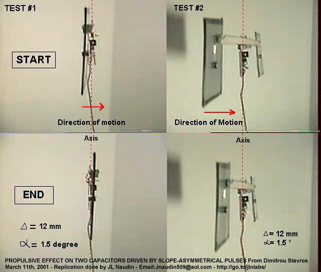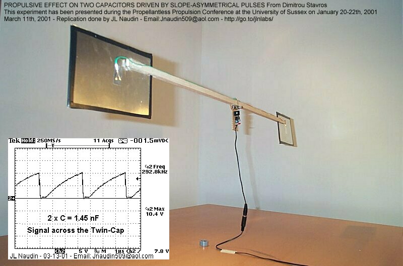
Propulsive effect on two capacitors driven by slope-asymmetrical pulses experiment
PRODUCTION OF DIRECTIONAL THRUST
created on March 4th, 2001 - JLN Labs - March 18th, 2001
This is the replication of the
Stavros' device for developping a directional thrust and it is
very close to the original setup.
This device has been presented at the
Propellantless Propulsion Conference at the University of Sussex
on January 20-22, 2001
and fully explained in the paper "Efforts in
developing upward and directional thrust" by Stavros G. Dimitriou
| Characteristics
of the tested apparatus Total
measured capacitance of the two capacitors
: 1.45 nF Some advices : The device is very
sensitive to the air motion in the
room, cautions must be taken before each test run :
|
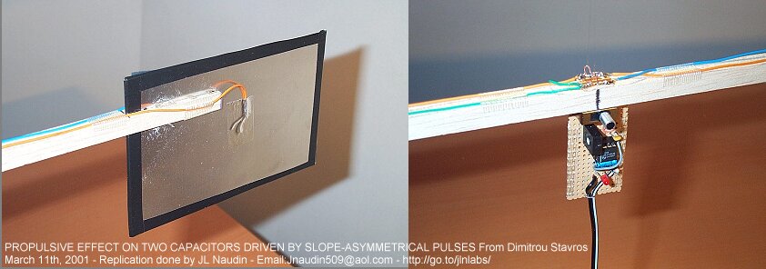
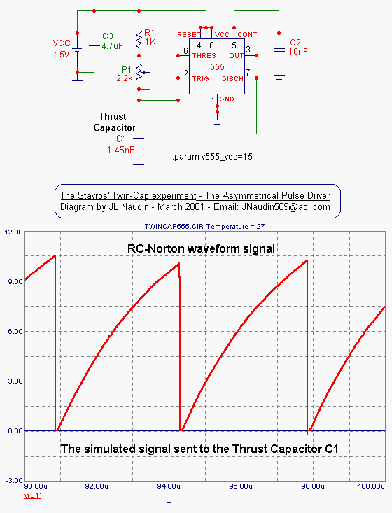
The original Stavros' diagram has
been used for this experiment
The measured signal shape (below) sent to the Twin-Cap (C1) is
fully in line with the RC-Norton waveform simulated above.
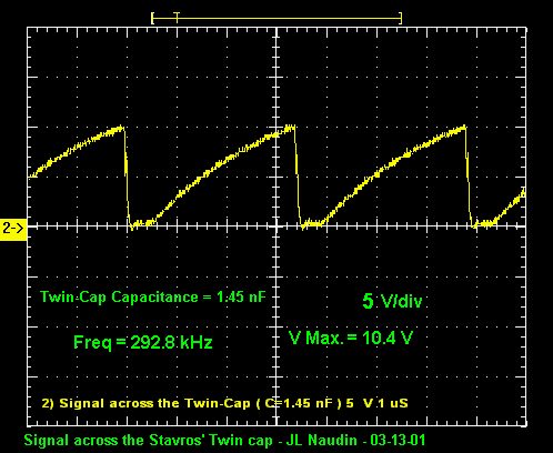
The Real signal measured across the Twin-Capacitor
" With the measured capacitance of 1.45 nF
for the two capacitors, the fundamental frequency of the waveform
should be ![]() = (1/(2*pi*1.45nF*376.7
ohm)) = 291.378
kHz (theoretically) or close to
that as possible in practice ( Z0 is the free-space impedance (
see formula (11)
). A peaking of
the output thrust is observed when this condition is fullfilled."
- Stavros Dimitriou
= (1/(2*pi*1.45nF*376.7
ohm)) = 291.378
kHz (theoretically) or close to
that as possible in practice ( Z0 is the free-space impedance (
see formula (11)
). A peaking of
the output thrust is observed when this condition is fullfilled."
- Stavros Dimitriou
See the Videos of the experiment ( below )
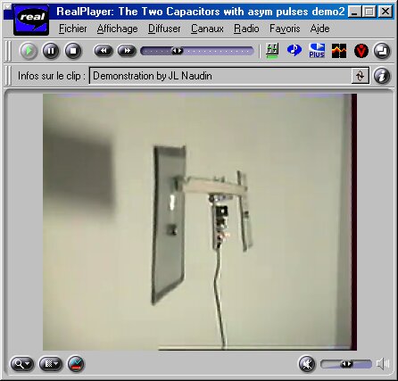
Download the Video of the test ( size 377 kb )
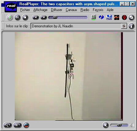
Download the Video of the test ( size 264 kb )
To see thess videos, the free
downloadable RealPlayer is required ![]()
 The
Stavros' Circular Transmission line experiment
The
Stavros' Circular Transmission line experiment
 Efforts
in developing upward and directional thrust
by Stavros G.
Dimitriou
Efforts
in developing upward and directional thrust
by Stavros G.
Dimitriou
Return to the Field Effect Propulsion page