
The
Lifters successful replications
Experimenters
Log Book
reated
on October 10th, 2001 - JLN Labs
- Last update May 31, 2002
All informations in this page are published free and
are intended for private/educational purposes and not for
commercial applications
Note from Jean-Louis Naudin : I shall be very glad to publish all successful Lifters replications in my web site so, don't hesitate to send me the photos, the diagrams and the videos of your experiments.
|
||||||||
| Envoyé via Internet | ||||||||
Jean-Louis,
Another successful lifter. (see attached)
Set up in three hours, but had to troubleshoot for an hour before
it was sustainable.
Longest flight has been 35 minute so far.
Gary Ward
Houston, Texas, USA
|
||||||||
| Envoyé via Internet | ||||||||
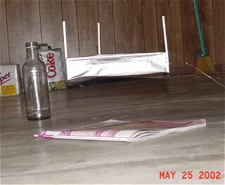
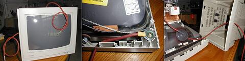
Good morning Jean-Louis,
Per your Lifter Replication page, I wanted to report my successful lifter replication from last night. Attached are a few pictures of the lifter in action along with my modifications to the computer monitor power supply listed on Tim Ventura's http://www.americanantigravity.com web site that makes it more portable than an open monitor case.
Thanks,
Jeff Baker Arlington, Texas USA
|
|||||||||||||
Hi all,
I'm new to this group so I'll briefly introduce myself: I'm 28,
living near Paris, France, and I'm currently employed as a senior
IT developper.
As the subject said, I successfully replicated the Basic Lifter,
and I uploaded some pics and a video at http://lab.guerizec.net/gallery/Basic
I have some new design in mind, and I'll keep you updated when
they're ready, of course.
Have a good week-end.
David Guerizec
Click on the picture to see the photos and a VIDEO
|
|||||||||
| Envoyé via Internet | |||||||||
Hi !
Greetings from Norway! Excellent site ! I've finally sucessfully
replicated the lifter using a simple flyback inverter as a power
supply.
This is almost too cool to be true (I have to start rereading all
my "mad science" books).
Regards
Hans J. Grimstad
Norway
|
|||||||||||
Hey :-)
Finally at last, got one to fly, it might look a bit shonky, but
it works well.
I call it the X Wing, i dont think ive seen one exactly like
this one.
Hope your all haveing a good day/night
Bye
Nick.
|
|||||||||||
Jean Louis,
I am glad to announce that today I successfully replicated your lifter 1 Design over here in Belgium
I made some modifications to the dimensions based on the successes of other lifter designs. As a next step, I plan on experimenting using other shapes, trying to enlarge the path of the field lines.( if insulation would seem to be possible, try to have 2 intersecting lifter stages) The flight was somewhat unstable, but it clearly lifted.
You have done a very good job on your website! Keep up the good (scientific) work!
Kind regards,
Hans
Ameel
Kortrijk, Belgium
|
|||||||||||
| Envoyé via Internet | |||||||||||
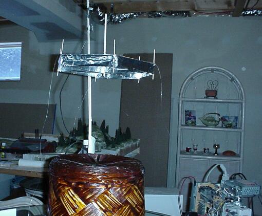
Hi Lifters!
Applied Electrogravitics strikes again with the new,
unbelievable and exotic 6-foot (2-Meters!) Beamship Variation
III. Just look at the photos!
I almost would not have believed something so big and heavy could
degravitate with such astounding upward force with such low
power!
It is SO impressive and awesome in flight; the pics and video
don't do it justice. This technology CAN be scaled up with no
limit yet in sight!
Except now, to build larger Beamship series electric spacecraft,
Applied Electrogravitics is forced to find larger facilities.
Say, an abandoned aircraft hangar in SE Pennsylvania (TT Brown
Territory).
Beamship is equipped with full space-frames, SEARL IGV-style landing gear (they are designed to/can support Searl's multi-ton IGVs), uncovered saucer framework. This is my favorite spaceship yet, and, its much quieter. Looks real impressive on floor and in flight! Full frames and cabin, ready for covering with mylar, etc.
Beamship Variation III - Specifications |
| Weight: 42 grams Width: 6 feet on each side (2 Meters) Height: 18 1/2 inches Anode wire: #40 Stainless Steel Wing foil height: 2 inches Spark gap: 2 3/4 inches Ambient temperature: 71 degrees F. Amb. relative humidity: 68 % date: sunday, May 12th Timestamp: 1:55 pm EDT Beamship is weightless at: 30,000 Volts straight DC @ .85 mA current. That's about 25.5 Watts. |
Beamship Variation III is in a stable neutral hover 4 1/2 feet off the lab floor at: 35,000 Volts (35KV) @ 1.35 mA current. That's 47.25 Watts for a 2-meters (largest ever in the world - call Guinness), 6-foot wide scale model electric spacecraft. Still has plenty of upward thrust at full power.
Will test for payload, but my best guess is 4-5 grams payload at 1.5mA @ 37KV.
The bar has been raised, and Applied Electrogravitics adds yet an even larger and better Beamship to its rapidly growing space-fleet. This is a nice size for onboard power and radio control. Look at my single-channel outboard RC, hooked up to power supply. Not much, but its a start... just neet to add 3-more channels for full RC. Ciao, fellow space-lifters, we are in the final space age...
Russell
Applied Electrogravitics

Click on the picture to see the photos, details and VIDEOS
|
|||||||||||
Hi Jean Louis
I have finally got a lifter1 to fly! I have built numerous
versions but all were too heavy to take off. I found that if i
suspended them sideways I could see that they were generating a
little thrust.
my successful lifter was a 20cm equilateral triangle. I folded
the foil over and didn't have any balsa wood under it (this made
it very weak but it could still hold its shape). the upright
struts were about 0.5mm square balse wood and the wire was very
thin copper wire pulled from some other wire, suspended 4cm from
the foil.
the power supply is an old 14" monitor giving 22-24KV.
I have not yet taken any photos, but hopefully will have some
soon.
loaction is: Palmerston North, New Zealand. latitude 40.2 S,
longitude 171.8 E
thanks for all the info on your web site.
Andrew Murphy
|
|||||||||
| Envoyé via Internet | |||||||||
HERE ARE PHOTOS OF THE FANTASTIC 3-FOOT DIAMETER BEAMSHIP
VARIATION I AND THE EVEN MORE INCREDIBLE BEAMSHIP VARIATION II.
BEAMSHIP VARIATION I USES #35 ENAMELED MAGNET WIRE AND EMITS A
SLIGHT HISSING SOUND IN FLIGHT.
BEAMSHIP VARIATION II IS A GARGANTUAN FOUR FEET IN DIAMETER
AND HAS LANDING PODS AND USES #30 MAGNET WIRE. VARIATION I IS 17
GRAMS AND LIFTS A PAYLOAD OF 6 GRAMS AT 1 mA AT 40KV STRAIGHT DC,
VARIATION II I HAVE NOT ADDED A
PAYLOAD CABIN AND SUPERSRUCTURE TO YET, BUT AM SWITCHING TO #50
STAINLESS STEEL MAGNET WIRE FOR NO NOISE AND EVEN MORE LIFT! I
HAVE EXTERNAL SINGLE CHANNEL (MAIN LIFT) FOR BOTH (HAVE A PCM
COMPUTER RADIO XCEIVER MODULE ATTACHED TO POWER SUPPLY) SO I CAN
CONTROL FROM HALF A MILE AWAY, AND THEY GO FROM THE FLOOR TO THE
CEILING AND CAN HOVER REALLY STABLY AT ANY ALTITUDE.
THE THRUST IS TREMENDOUS! I USE A GAMMA HIGH VOLTAGE RESEARCH
POWER SUPPLY WITH CURRENT LMITING FROM 0 TO 1.5 mA, AND VARIABLE
VOLTAGE FROM 0 TO 40,000 VOLTS. wITH SQUARE WAVE PULSING, CAN
LIFT U TO FOUR TIMES THE PAYLOAD I
CURRENTLY ENJOY. CIAO STEVE AND ALL MY FELLOW LIFTERS!
Russell
Applied Electrogravitics
Click on the picture to see the photos and details
|
Dear M. Naudin,
On april, the 21st, 2002 I had my successful replication of the
lifter 1 experiment. The lifter hovered very stable.
The HV supply was made with a 14 inch color monitor.
With best regards,
Carsten Spanheimer, Tuebingen, Germany.
Click on the picture to see the photos and details
|
Hi Jean-Louis,
I've successfully replicated the Lifter1 - thanks for your
instructional web pages! I've put together a web page at http://www.zikzak.com.au/zik/lifter/
describing my experiences. Feel free to reproduce the photos from
there if you like. There's also a rather poor quality MPEG video.
Next I'm going to look at making a lightweight AC power supply
suitable for use with a flying model. I'm also interested in
trying to detect mass loss or positive charging in a closed
system to attempt to verify that electrons are acting as reaction
mass.
Zik Saleeba
Melbourne, Australia

Click on the picture to see the photos and details
|
Tout à l'heure, avec un exmoniteur vga, et
l'aide de vos très claires explications, j'ai fait décoller, du
premier coup un Lifter de 20x20x20.
Bruissement, odeur d'ozone et très nette perception d'un flux
frais émis par l'appareil.
Bien entendu j'ai respecté les mesures de sécurité
indispensables et n'ai eu aucne surprise, sauf une : ca vole!
J'avais découvert votre site il y a quelques mois lors d'une
recherche sur les microondes et il m'a été à nouveau signalé
par ZZZ ,
Félicitations et merci pour la pédagogie du site et pour toutes
les questions que pose cette manip réussie.
Matthieu Filippi
Afa. Corse du sud
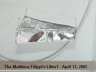
Click on the picture to see the photos and the videos
|
|||||||||||
| Envoyé via Internet | |||||||||||
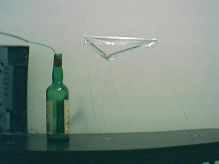
Bonjour, M. Naudin!
Here is a picture of my wildly successful third lifter and my website ( http://64.133.223.115/physics/ ) with all the details. I have to thank you for leading us in this endevour and compiling all of the information.
Keep up the great work!
Ben Nesbitt, Bellevue Washington
|
|||||||||
| Envoyé via Internet | |||||||||
Bon Jour! Thank you for the great information. It has been
quite inspriational.
I recently replicated your rotolifter experiment (with just one
lifter - simpler). My model making skills are lacking, so the
lifter was too heavy, but tests have got it to spin at 80-100
RPM.
I've also had some success with the designs involving a metal
cylinder and plate and the one using two cones. Neither fully
rotated on the test stand (reference my model making skills) due
to the large friction. More information will be coming once the
rotator arm is improved and more designs get tested.
Attached is a video of the rotolifter experiment.
Here is the information for your log book:
Wesley G. Faler
Ann Arbor, Michigan, USA
Roughly: Latitude: 42°10' N
Longitude: 83°26' W
Thanks again!
-Wes
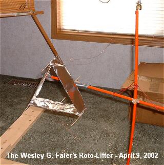
Click on the picture to see the photos and the videos
|
|||||||||||
Hi all lifters,
Today I successfully flew my RC lifter using helium balloons to
just balance out its weight. The motorised panel worked as
expected.

Click on the picture to see the photos and the videos
Enjoy it!
Regards,
Saviour.
|
|||||||||||
Hi Jean-Luis,
Thanks for the excellent instructions on how to build the
lifter! After a few turkeys that are too heavy to fly, finally
the 4th one with 9 cells took off, totally fascinating!It is
powered by a 14" color monitor. The flyback circuit I made
does not seem to provide enough current.I have no cameras so I
can not show the picture, sorry.
Here is some specifications of my lifter:
-9 cells, triangular lifter frame, each side of the unit triangle
is 160mm, from plastic drinking straws of 5mm diameter x 180mm
long.
-bamboo-made toothpicks as wire posts(which I boiled in wax
except 10mm from one end before use to prevent burn-up), 2mm
diameter x 60mm long. wire is
approximately 0.2mm dia.
-Aluminium foil 30mm x 150mm ( 9)
-Superglue (cyanoacrylate)
Construction tricks:
-Glue the foils to the straws 250mm from one end. roll the foil
around till it cover half the diameter of the straw. Glue the
rest of the foils to the straw WITH
THE SAME FOIL-STRAW ORIENTATION.
-Squeezed the 250mm foil-free end end of straw 2 and insert it
into the 50mm foil-free end of straw 1, then insert the 250mm
foil-free end end of straw 3 and
insert it into the 50mm foil-free end of straw 2...WITH THE SAME
FOIL-STRAW ORIENTATION.
-You should have now a strange looking "pole" of straw
and foil "flag". Lie it dow flat,join all the gaps
between foils except the 2 ends with litle piece of
foils with sticky tape, makde sure they are conducting.
-By bending at the 200mm + 50mm junctions in a particular way,
the final lifter shape is obtained.
THIS IS BEST EXPERIMENT BEFOREHAND DONE WITH A BARE STRING OF 9
STRAW TO SEE WHICH WAY THE WHOLE THING BEND.Glue certain joining
corners with glue to hold the shape. Squeeze and join the last
straw-straw juction, and tape the foil together as before.
- Take the toothpicks and piece the straw at/near the
apex/corners with the un-waxed end.Glue them to the frame. String
the wire, glue on the 3 legs at the 3 outer corners and you are
finished.
Cheers and Happy Experimenting
Vinny Lam
Melbourne, Australia
|
|||||||||||
Hi Jean-Louis,
I successfully replicated lifter 1 using a 0.5mA current limited
25kV DC high voltage power supply.
Now I am working on a more elegant and precize variant using
simple aluminium foil and 0.10 mm diameter steel wire.
I assume we need a perfect DC HV output signal generator to begin
experiments with harmonic ion-acoustic frequency chords a la
Keely. But how can
we most efficiently couple some frequency generators to the HV
signal output?
Please find some pictures of the first flight uploaded at
http://www.geocities.com/hizlimurat/lifter1.jpg
http://www.geocities.com/hizlimurat/lifter2.jpg
http://www.geocities.com/hizlimurat/lifter3.jpg
http://www.geocities.com/hizlimurat/lifter4.jpg
You will also find some videos there but you need a Divx MPEG-4
(fast motion) Codec reader to see the movies in your real player.
See for it on your DVD
driver CD.
http://www.geocities.com/hizlimurat/lifters1.avi
http://www.geocities.com/hizlimurat/lifters2.avi
http://www.geocities.com/hizlimurat/lifters3.avi
http://www.geocities.com/hizlimurat/lifters4.avi
Best regards,
Berkant
| (048) |
|
||||||||||
I made these about 3 months ago and at present I'm working on minaturizing the power source,heating the cathode ( possibly to incandesance using tungsten in a vacuum ), testing lifters in SF6 or freon R-12.
I'll write more when the results are in but in the mean time,
Thanks for posting all this info...towards optimization.
Dan
Click on the picture to see the photos
|
|||||||||||
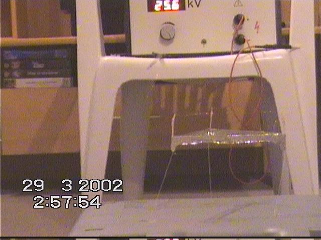
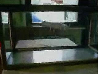
Dear Jean-Louis,
On saturday the 9th our group did 2 experiments which we would
like to share:
- Lifter flight in a closed box :
To clear the question for us wether a lifter would fly in a
closed box or not, we used an (empty and dry) aquarium(of glas)
of the dimensions:
H375mm x L775mm x B330mm.
The top of the aquarium was closed with a piece of wood with 2
small holes for the cables.
The results were that the lifter 1 flys as allways if not placed
to close to the walls of the aquarium.
We made a short video about this flying tests(320 x 240pixel with
a MC3 from Kodak. We recommend this cheap mini-camcorder from
Kodak, its really great !!)
- Flight video of Lifter 1 :
With our new mini-camcorder MC3 we made some small flight-videos of lifter 1.
Click on the picture to see the videos
Mit freundlichen Gruessen,
Stefan Kaechele
Laufenburg
Germany
|
|
||||||||||
Dear Jean, this is Tony Klose again.
The science fair at my school was a success!!! Guess what...
I won the first place prize in the seventh grade, and the grand prize over the whole school using the Lifter1 !!! I am so happy and I wanted to thank you for everything.
Thanks SO much!!!
Sincerely,
Tony
Klose
|
|
||||||||||
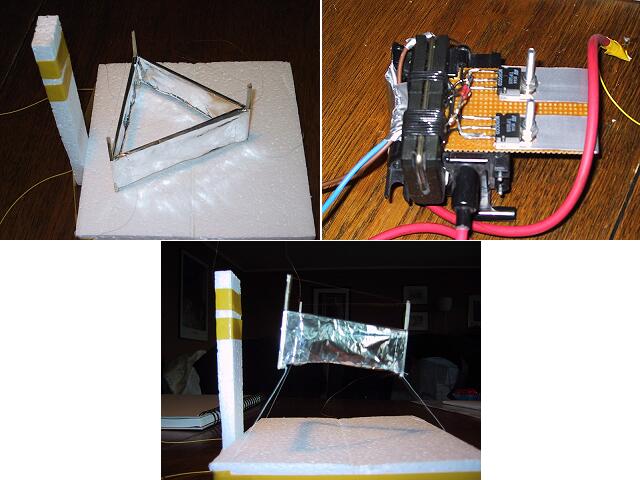
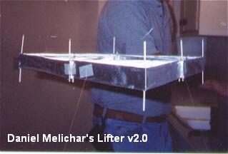
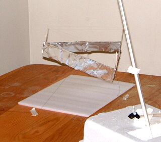
Dear Everybody:
This is a test of the lifter version #2, which contains an internal support-structure consisting of an additional 3 lifting surfaces. Essentially, it's one of the lifter V1 models placed inside an identical model of a larger lifter.
The power-output seems to be a little bit higher, and it is definitely more unstable on it's tethers. This could simply be due to weight-distribution issues from my construction or it could be something else entirely . . .more power, tether length, etc..
Thanks;
Tim Ventura

Click on the picture to see the photos and the videos
| (045) |
|
||||||||||
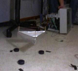
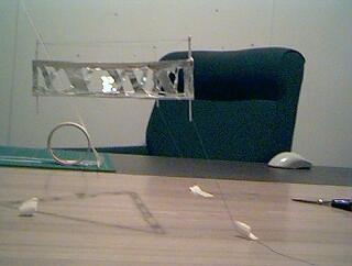
Dear Jean-Louis
Thank you so much for your assistance with my dysfunctional lifter.......
I made a few changes to it today and it now lifts off !!!
I'm not using tie-downs on it yet, so it currently doesn't do a whole lot (takes off, loops the wires, arcs, and drops), but I've tried using a guide and it climbs right up it -- at least 8 inches high (the plastic guide is only a foot tall -- and I'm holding it with my hand on top!)

Click on the picture to see the photos and the videos
Here is a lifter test-video that I took this evening. I used black tie-down threads on the table surface and the 14" computer-monitor for power. It levitates perfectly...!
Tim Ventura
|
|||||||||||
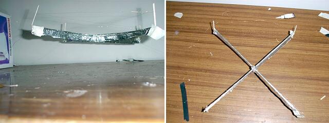
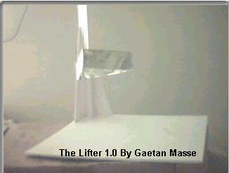
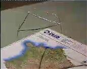
Good day
just to let you all know ... I have updated my lifter site www.eccdm.d2g.com
NEW Feb 23 2002 : The first stage of the rocket lifter. This lifter uses a plate in stead of wires for the plus side of the HV.

Click on the picture to see the photos and the videos
I am working with a lifter that does not use wires for the plus side of the HV...instead I am using a plate. The design can be built to use multi stages if needed or arranged like the SFPT thruster.
Gaetan Masse
|
|||||||||||
Hello.
This is Tony Klose again. I made 6 different versions of the Lifter 1 and two of them worked. One works really good and the other justworks a little bit. I have attached some photos of the better one.
Specifications:
It has an upper frame of balsa that is 80mm long and about 1 1/2 mm wide. I cut the balsa from a big strip of it. The tin foil is one long piece that goes all the way around the craft. The positive electrode is really thin copper wire that I took out of a regular cord that plugs into the wall. The TV that I am using is old, but it still gives enough power. I don't know how many Kilo Volts there are though. The vertical sticks are made of thin balsa. It is a small lifter but it is really cool. Im going to use it in my science fair at school. I also don't know what it weighs, but it is very light.
My location is Shawano , Wisconsin. I don' t know what the latitude and longitude lines are though, but it is in north east Wisconsin. Well, good luck. I will inform you of any updates.
Best regards,
Tony Klose
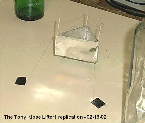
Click on the picture to see all photos and details
|
|||||||||||
Here's another one for your page:
today i built and tested lifter v1.02 (third lifter 1 attempt)
design parameters as follows:
150mm wide on each side
30mm wire gap
25mm foil hight
1cm legs on bottom
this time i ripped the 5mmX3mm balsa in half length wise to yield
~2.5mmX3mm
balsa rails to reduce wieght
i glued foil over the top of each arm like jln's ufo lifter.
turned on power
one side went up
i shut off the lights and looked to see where the corona was
leaking
i added a little black tape to the corners and moved the negative
electrod to the center of the foil instead of the corner
im happy to report that i finally have a fully functioning
lifter.. it was great. my family got a kick out of it..
especially my dad lol..(suggested trying to lift the table as a
later goal lol)
one thing tho.. it arched pretty often, even when it was floating
pretty stabley. my mom thought it was fantastic how it arched
like that in the air.. it looked really marvelous, tho
undesirable.
thank you guys for the feedback. it really solidifies the reality
of the technology when you see it in action for your self..
may the lifting force be with you (stolen from jean-louis
<GRIN>...i'll pay royalties, i swear...lol)
Mike
|
|||||||||||
Here's another one for your page:
I must say I was amazed at how totally simple it was to run this
experiment, thanks to the excellent information on your website.
- Ed Hutchins

Click on the picture to see all photos and details
|
|||||||||||
Success at Last! Persistence does pay off. Mike and others, don't give up.
Finally received my new digital scale (which I ordered over a month ago). When I weighed my old, patched up lifter, it came in at 7.6 g. No wonder I could never get that turkey to fly. It was built to JLN's specs. I even used smaller balsa wood, than specified, so I thought it would be lighter than JLN's. Of course each time I modified it, or patched it, it kept getting heavier. I still don't know how JLN got his to be so light: only 2.3 g. Maybe they have lighter balsa wood in France:-) Or, maybe I used to much super glue gel.
So, out with the old and in with the new. New lifter uses 3 mm diameter x125mm long, light weight plastic straws (actually coffee stirrers) for top foil frame. The straws are much lighter than 2x2mm balsa and already have the rounded shape for the foil top. The lifter is slightly larger than JLN's Lifter 1. It is a 230 mm triangle, due to the length of the straws. It weighs about 3.8 g. I was afraid that it wouldn't fly, since it exceeds the total weight of JLN's Lifter 1 plus payload. However, when powered up by a 15" computer monitor, she leaps into the air! Success at Last!
I had my tie downs arranged differently than most. I had 3 strings from each leg that were tied together at some point, with a single string going down to the table top. My lifter flew to the top of the string, then apparently due to some asymmetry in thrust, she slowly veered over to the side until the thrust was more sideways than vertical, and then she promptly fell on her side to the table. Changing the tie downs to the more common one string per leg corrected this problem and now she flies straight and true just like in the videos. I think that this demonstrates to all those who say that lifters are unusually stabile that this is not true. The stability comes from the tie downs, not the lifter itself.
Now, I just have a little arcing problem that I need to correct. When it arcs, the lifter immediately falls to the table.
Construction Details:
New lifter uses 3 mm diameter x125mm long light weight plastic straw (actually coffee stirrers) for top foil frame. Not all straws are lighter than balsa wood, choose your materials carefully for the lightest weight. If you don't have a scale, you can compare the relative weight of your materials by making a crude balance by balancing a piece of balsa across something round, like a pen. Then place an equal length of balsa or straw at the same distance from the pivot point, it should immediately become obvious which material is lighter. Use the lightest material that has sufficient strength to do the job. Wash your hands before working with balsa vertical supports, since finger oils can make balsa conductive enough to catch fire.
Construction of the frame is a piece of cake. Make a single lengthwise slit 1cm long in one end of each straw. Close up the slit end and insert it into the open end of the next straw, along with a drop of gap filling super glue. Make 3 pairs this way, then line up all 3 pairs side by side and use a ruler or such to bend the straws all in the same place.Close up the slit end of each pair and insert it into the open end of the next pair, orienting the bends, until you have a triangle. Glue if desired.
Don't use a bottom frame, it is unnecessary weight.
Next cut a long strip of aluminum foil 4cm wide. Put a bead of gap filling super glue along the outside of one side of the triangle. place it on the foil 1cm below the foil edge and leave some extra foil at the end. Hold firmly until the super glue sets. Use an Exacto knife to remove a small rectangle of the upper 1cm foil to allow clearance for the corner post. Apply super glue to the next side of the triangle and then roll the fame around and press it against the foil as before. When you reach the last corner, leave a 1cm flap of foil to wrap around the corner and glue to the other foil. Place another bead of glue along the inside of the 1cm foil edges and roll over the top of the straws for a nice rounded edge.
Vertical supports are 3 pieces of 2x2mm balsa wood 11cm long (should have made them longer and cut to length after gluing - one got glued in the wrong place! Vertical support acts as both legs and wire support. You don't have much to glue the vertical supports to, except the foil. You will need another balsa support temporarily inside the foil corner to support the foil during gluing. Make sure this support is treated with some kind of lube or something so it doesn't get accidentally glued to the inside of the foil. Mark the balsa supports 4cm from one end, apply super glue to the supported foil and attach the vertical support with the line even with the foil top and the 4cm sticking in the wire support direction. Squeeze the foil between the to balsas until the glue sets. Repeat for other corners. Allow super glue to set over night before attempting to install the wires and tie downs. Always allow super glue to set overnight before testing to prevent fires.
Check the weight of your lifter. If you don't have a scale, you can use the crude balance technique as described above. A US dime weighs about 2.2 g. JLN's Lifter 1 weighed just over 1 US dime. Mine at 3.8 g weighs a little less than 2 dimes, but it is slightly larger. If your lifter is not in this range, you are likely to have a problem getting it to fly. I realize that this only helps if you happen to have US dimes. Maybe others can give the weights of similar coins in other currencies, to help those who don't have scales.
All for now,
John
|
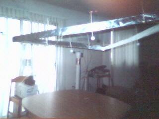
|||||||||||
Hello Jean-Louis
BB Racer photos...
Click on the picture to see all photos and details
Here are the BB Racer photos, built exactly the same as the lifter but in the horizontal plane and suspended from the ceiling. Tissue paper is used to fill the back half of the racer. Because it travels at 4 metres per second the BB Racer needs to be reasonably aerodynamic. The nose is a plastic needle this is to add a bit of weight to hold the nose down!
Lifter Photos.......
My lifter is a replication of JLN's and works very well.
Good experimenting, all the best
Neil McPherson.
|
|||||||||||
Dear Jean-Louis,
Bonjour M. Naudin,
Ma gratitude pour votre site et votre travail. Vous êtes une source intarissable.
De ce pas je vous envoie une photo d'une réplique en fonction du modèle HCD-03 de M. Claude Dupré.
Pour moi, la prochaine étape consiste en l'accumulation de métrique sur un des élements de base soit, un fil et une plaque, afin de batir une théorie d'ingénerie. J'ai le but de maîtriser la combinaison des variables évidentes : dialectrique, champs de force électrique, voltage, fréquences, capacitance et géométrie d'agencement.
Encore une fois, merci...
Cheers
Serge Deragon St-Basile-Le-Grand Québec, Canada
|
|||||||||||
Dear Jean-Louis,
our working group was able to replicate the lifter 1 experinent
succesfully.
Details:
humidity 38%
temperature 20°C
High voltage supply is a EHT multiplier(from a university) with a
max. of 50KV pure, not pulsating DC, voltage finetuning, change
of polarity, and scales for the actual OUTPUT voltage and
current. current up to 2,5mA.
Device was lifter 1 with adjustable wire and weight of 3g.
The shapes of the top part of the foil were mostly very well
rounded !
wire CuL with 0,16mm diameter
The wires from the high-voltage supply were partially covered by
teflon.
Results:
--------
lift-off voltage with 31mm wire distance was 18KV and a current
of 250uA
lift-off 25mm
15-16KV 250uA
lift-off 20mm
14KV 450uA
polarity on the wire in all 3 cases was minus !
weak hissing sound.
if you start calculating the lift-off power is between 2,2W/g and
only 1,3W/g.
AND I think the loss current can be calculated as about 200uA, so
the real force for the lifting effekt would be in the cases
above only about
250mW/g
we did a video of the lift-off and if you want I can send a
picture of the high voltage power supply connected to an
oscilloscop.
Mit freundlichen Gruessen,
Stefan Kaechele
Laufenburg
Germany

Click on the picture to see all photos and details
|
|||||||||||
Hi Jean-Louis,
Jeff Brown asked me to send you pictures of his lifter
helicopters (while he gets some sleep). They're a little
unstable, but they fly!

Click on the picture to see all photos and details
|
|||||||||||
Hi JLN,
I'm was impressed with your work on you site since 1996-7, when I see it for first time, and I'm very grateful for all you effort on every experiment, test, etc as it must take a lot of time (and money) thanks you!
Today I was testing another configuration for the lifter (see
pic below). It has 5 basic cells, spaced 2 cm, plate is 3 cm tall
x 15 cm cocking aluminium, wire is thin nude copper 3-3.5 cm
above the plate, frame of balsa wood. Flyes very well, very
powerful compared to the triangle lifter (that I build first, see
photos), but a bit unstable.
Power supply was a DC (how do you pulsed the HV??), flyback, 2 x
3055 and tripler type, connected to around 30v.
HV was 30kv I think (sparks very bright of 3 cm), I don't take
measuraments to it, nor at the weight.
All pics are of the unconnected device. There are movies if
someone ask, drop me a line.
Thanks again, Juan Barrios, Buenos Aires, Argentina (latittude 34, long. 58) :-)

Click on the picture to see all photos and details
|
|||||||||||
Hi Jean-Louis Naudin,
We finally got a lifter to fly.
The project is based on "Lifter 1" web page.
The lifter is buit of balsa tree(~2 X 2mm) and the copper wire is
about 0.25mm thick. We used an old 14" monitor (24kV) as
power supply.
We noticed that the lifter couldn't fly if we started from the
floor. We had to place "legs" under it to raise it
20mm..
The gap beetween the copper wire and the foil war reduced (from
org. 30mm) down to 28 - 26mm, this beacuse of the low power
supply.
We suppose that the lifter would have flown better if we had a
power supply higher than 24kV.
But anyway...it worked!
Greetings from North of Sweden (Umeå)
Magnus Tjällgren and Pontus Pursiainen, University of Umeå
|
|||||||||||
Dear Jean-Louis Naudin,
Hello! I have been out of touch for several weeks. But I
wanted to let you know I have constructed 13 lifter frames; of
them, numbers 7, 11, and 13 have flown. The 13 is
nearly a meter across!
I still don't have a scanner, but as soon as I do I'll send you
some photographs.
Speaking of photographs -- I've made many HI8 movies of the
devices in flight. On one recording -- taken in my garage,
after sundown, with dim illumination -- I noticed a peculiar dark
band running from the wire to the upper edge of the foil. It
persisted throughout the video, was invisible to the eye (I could
see it only in the recording), and I've not been able to
reproduce it. I wondered if you'd ever seen anything like that.
At any rate, my 14" PC monitor power supply is still
working, and I have many more frame designs to test. I'm using
3/16" balsa wood from the
frame, and aluminum foil for the vanes, and I finally found a
spool of loudspeaker wire with very fine gauge shielding wrapped
around the conductors -- 35 or 40 gauge, I think. It takes
forever to unwind, one strand at a time, but it makes excellent
lifter wire.
That's all for now. Good lifting, my friend!
Frank Tuttle
USA
|
|||||||||||
Hi guys,
Today I have tested and confirmed that vertical stacking works
very efficiently, and is quite easy to implement. This is how I
did it: Starting from top is the anode fine wire, then 40mm below
is the foil, following are a number of stacked foils with the
same 40mm separation between them. No wires in between as the
sharp lower edge of the foil acts as a fine wire. Make the top
part of each foil as smooth and round as possible and the lower
as sharp as possible.
Connect the positive to the top wire and loop the positive
skipping one foil at a time. Do the same for the negative
starting from the top foil and ending at the lower foil.
Preferably you should have an odd number of foils so as to end up
with the highest and lowest foils negative. A 3 stacked basic
lifter lifted 8g whilst a 2 stacked Dupre type lifters (weighing
8g lifted 18g!!, I should add another stack to this, possibly
providing about 28g lift or maybe more. For this
lifter I am using 50mm gaps and about 40Kv or a bit more. Lift is
being calculated by adding weights in a plastic container glued
in the centre. Weights used are pieces of thick wire cut to weigh
0.5g each.
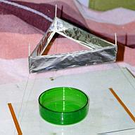
Saviour.

Click on the picture to get more details
2 vertically stacked hexagonal lifter. 1/2 Kinder egg (0.5g) on top used as container for loads. Air gap between foils is 50-55mm, foil is 20mm each. Note round smooth edge on top side of foil and sharp edge on lower side of each foil. Note that leg supports are not decorative, they are necessary to minimise field effects between the lower edge of the lower foil and the table, even if used on an insulated base. This lifter weighs 11g and lift an additional weight of 19g including weight of container. Top wire and bottom foil are positive (connected together), the middle foil is negative.
See more photos and technical datas at : http://bel.150m.com/
|
|||||||||||
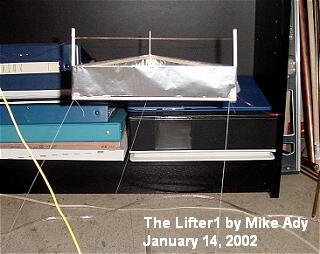
Hi Jean-Louis,
You can add 53N latitude and 113W longitude (Edmonton Canada) to
your Lifters map, if you like.
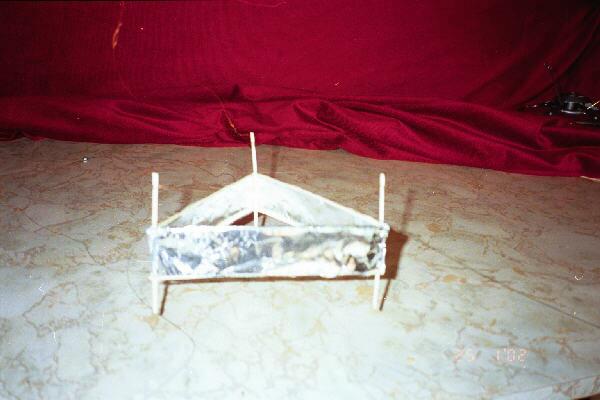
I finally got a lifter to fly. I built a balsa frame according
to the dimensions on your "Lifter 1" web page, except I
allowed room for a greater separation between electrodes. I still
don't have a supply of fine wire, so I used 0.25 mm bare copper
wire for the anode. I first tried an electrode separation of 38
mm and wrapped a single sheet of aluminum foil (650 x 40 mm)
around the frame for the cathode. The leakage current was too
high, probably due to the sharp leading edge. There was no
measureable thrust (less than 0.3 g) and very little electric
wind. Next I cut a 650 x 45 mm piece of aluminum foil and I
"gently" folded over the top 5 mm of the foil (i.e. no
sharp crease) and this time, the lifter skidded across the floor,
but failed to lift off. I moved the aluminum foil up until the
separation was 36 mm, and finally it lifted off. The leakage
current was still very high, but could probably be reduced with a
greater radius of curvature on the leading edge of the cathode.
Regards, Mike Ady
|
||||||||||
I have been waiting for this moment for months now,
I have FINALLY achieved success with my lifter. After weeks of
troubleshooting such a simple design, I got my lifter to lift
off. What an amazing feeling.
Flight is very unstable, but VERY cool to watch. My mom loved
it.
A very heartfelt and sincere thank you to Jean-Louis Naudin, This
would never have been possible without you. Also thanks to
everyone else in the group who was willing to help a young
amatuer like me out.
Good luck and fair travels to all,
James
|
|||||||||||
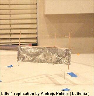
Dear Jean-Louis
I am sending to you pictures of Lifter 1 replica.
Experiment was succesfull. At first there was problems with
discharge between electrodes, but after aplying oil on the wire
and foil edge discharges stoped.
Lifter specification:
Edge length 150mm
Weight 1.4g
Height 100mm
Foil width 40mm
Distance between wire and foil edge 33mm
Wire diam. 0.25mm
Supports made from balsa
Powered with ViewSonic 14 monitor
Best regards
Andrejs Pukitis
Riga,
Latvia (Lettonia)
|
|||||||||||
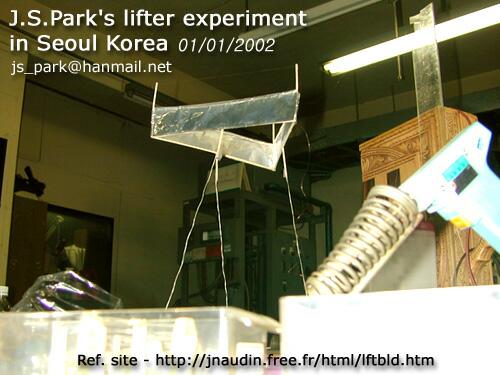
Dear Jean-Louis Naudin
I was impressed deeply by your great work!!!
So, I tried the replication experiment.
I used the lifter1 design. And I made the about 40kV HV power
supply using by 15kV, 20mA neon transformer and voltage doubler
circuit. The resistor used in the circuit in order to prevent arc
disahrge between two electrodes on the lifter1.
The experiment was successful and I'm very pleasure!!
I'll send you more results later.
Sincerely yours.
Happy new year everyone!!!
Jung-Seo Park
http://ironrose.soongsil.ac.kr
jspark@ironrose.soongsil.ac.kr
js_park@hanmail.net
|
|||||||||||
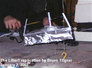
Bonjour Monsieur Naudin.
Just wanted to inform you that we managed to get a successful
lift off of a Lifter version 1 using a 24 KV power source on
December 22. We had to raise the positive wire to a height of
40 mm due to arcing. This was probably due to humidity in the
room at the time. Though lift was unstable it was definite
lifting to a tethered height of approximately 1 foot above the
launch surface. Construction was to Lifter 1 specifications using
a single sheet of foil for the capacitor, 40mm in height, three
straws for the frame with three coffee stir-sticks as the support
struts for the positive charge wire. The Lifter only lifted on
two sides until we moved the ground to a position diametrically
opposite to the power source connection to the lifter.
Currently we are looking to increase our power source capability
before continuing with our experiments.
Here are the photo's of our first lifter flight test of December 22, 2001 as mentioned. Please feel free to post them. Since then we have had several more succesful tests using smaller lifters of approximately 120mm per side. We hope to use these as the basis point for testing various configurations. Rather than use three tether lines we rigged a guide line through the centre of the lifter and used a single line as a tether in order to reduce weight. Another method we considered using was to attach two guidelines to the ceiling at a slightly greater width than the lifter and attaching it to the launch surface inside the Lifter itself. Thus as the Lifter rises it will eventually slow itself down to a height based on on the angle of the two guide wires. Though this causes some stress on the frame it does allow for a lower take-off weight and thus a lower level power source can be used.
Regards,
Bruno Tilgner
|
|||||||||||
Hi,
My first working lifter is based on the Keops1 from Stéphane Bernard.
The pic can be found at http://earth.vol.com/~lostroad/l1.htm

|
|||||||||||
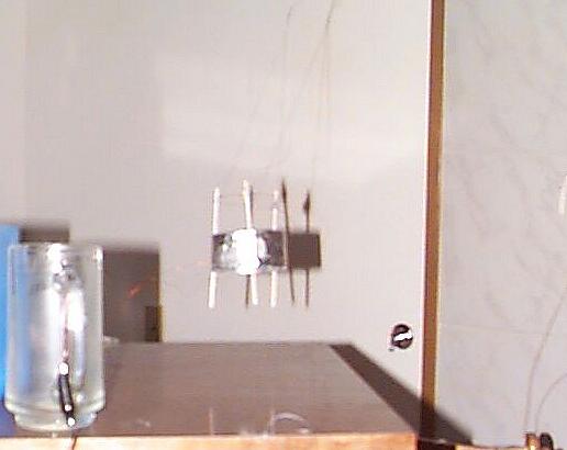
I've made a simple low-power design. Cylinder
with 3 drink stirring straws to hold the thin wire at a distance
of nearly 40mm(the air is moist and conductive in Washington,
needed some extra distance to prevent arcing.) above the foil,
which was formed on the end of a tall cup to have an inward curl.
The whole assembly would pull towards the ground wire, even the
length of wire that was en route to the device. I suspended the
frame with thread to the ceiling, and then tied it away from the
ground wire(no more crashing into it and arcing!). Now we get
the lifted effect you observe in my pic =]
it's kinda fuzzy, I'll have to send you a better picture sometime
soon, maybe with a better device as well =p
Happy Holidays ^_^;
-Shanjaq
|
|||||||||||
Hello all,
I constructed a small cylindrical lifter using aluminum foil
drinking straws, and copper magnet wire. The cylinder is the same
diameter of a cardboard toilet paper roll. The drinking straws
are the type that come with juice boxes. The cylinder is 2.5cm
high. Taped to the cylinder are three sections of straws. Taped
to the straws is a loop of copper magnet wire. The wire is just
under 2.5cm above the aluminum cylinder. The power supply is a
100kV generator powered by a 12V security system battery. I
estimate that the generator is actually putting out just over
20kV, based on the fact that sparks can't jump a spark gap
greater than
about 2.5 cm. When I switch on the power supply, the lifter
quickly lifts to between a half centimeter and a centimeter off
the table and floats around a bit. When I switch off the power
supply, it falls back to the table. I believe that the weight
and/or stiffness of the charging wires is preventing it from
lifting higher.
I am very excited, as this is my first lifter to actually fly. Also, it requires only 12 WATTS!
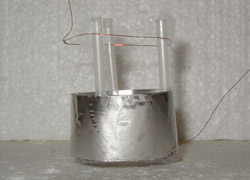
Here is the link to my 12 watt lifter page:
http://www.imagineanything.com/energy/projs/lift01.htm
Tony
|
|||||||||||
Hello Mr. Naudin,
Here are a couple of pictures in black and white of the lifter I
built this week end.

Thanks for the info on the spark gap.
Best Regards,
Andy Alcon
Fort Worth, Texas
|
|||||||||||
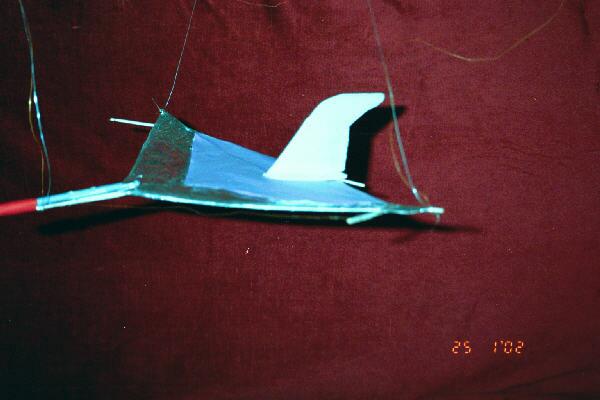
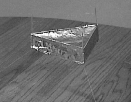
Chers Jean Louis
Je reprends contact avec toi afin de dire que j'ai créé un
nouveau type de lifter .
Je l'ai nommé le Keops 1 je te laisse imaginer
pourquoi ...
J'ai voulu augmenter la poussée du basic lifter ce qui m'a
amené à créer cette nouvelle forme ...
Keops a décollé hier soir vers 22h30.
Keops utilise les dimensions du basic lifter soit
12 cm de coté construit une pyramide à 3 coté fil de cuivre à
3 cm comme pour le basic. Au sommet de la pyramide construit une
petite boule d'alu connectée au +, secouez le tout, mettez sous
tension et hop IL VOLE !!!!! :-)
Voila, j'ai pensé a cette structure pour que la poussée
produite par les 3 cordons converge vers un point ...
J'ai ajouté la sphère d'alu afin d'augmenter le
"stress" en ce point...
Bon courage Jean Louis
Cordialement
Stephane BERNARD ( FRANCE )
Click here for more informations about the "Keops1" Lifter
|
|||||||||||
Hi,
I successfully replicate lifter v1.0. I am sure that my Prof.
will be very interested to see it on Monday.
A few of quick and dirty experiment gave the following results.
------------ experiment #1 ------------
Conclusion:
The voltage required to take off (lift) by itself is bigger than
what is required to keep it afloat.
Experiment:
- Set voltage to minimum, turn on power supply, the lifter
does not take off.
- Slowly increase the voltage, until the lifter lifts
- While it is in the air, slowly decrease the voltage.
But the lifter will still be afloat, even if the voltage is
below what is required to take off.
----------------- experiment #2 --------------
Conclusion:
If the voltage is too low for the lifter to take off by itself,
you can blow light wind (from your mouth) to induce the lifting
process
Experiment:
- Set voltage to the level that is required to keep it afloat
(from experiment #1). Turn on the switch, nothing happens.
- Blow light wind, the lifter moves side way and the go straight
up.
---------------- General Setup -----------
Power supply: PC Monitor (Sampo Alphascan 15)
Lifters: Version 1.0 from Jean-Louis website Minimal sparks,
corona during the experiment.
Happy lifting, and be careful,
Teepanis Chachiyo.
|
|||||||||||
Hi all
I thought that I might make it official and give the url to my lifter site : http://www.geocities.com/gmasse.rm/lifter.html
I learned alot from this project. Its been some thing that I
wanted to work on since I recieved my first info on the lifter
from Information unlimited back almost ten years now.
I am using a Samsung CVP4237 colour monitor.
The lifter has 200 mm width and about 30 mm to the top wire.
It is made of aluminum and balsa with copper wire.
The wire is a little stiff so it keeps the lifter from beeing
completely stable.
click on the picture to see Lifter1 videos from Gaetan Masse
|
|||||||||||
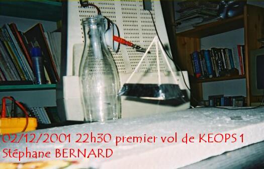
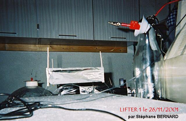
Jean Louis ...
Je reprends contact avec toi afin de t'informer que j'ai
repliqué avec succés le lifter 1 le 26/11/2001 à 22h30
Suite a de nombreux echecs liés a de mauvaix choix (fils, lifter
trop lourd,trop d'humiditée etc ...) et aprés corréctions,j'ai
reussi à repliquer ton experience .
Tu trouveras en fichier joint une photo de ce test.
Je vais continuer dans cette voie et tenter de
nouvelles manip.
Je t'enverrais de nouvelles images si je replique avec succés
d'autres manips.
Cordialement
Stéphane BERNARD
Lien vers le site de Stéphane : http://moumra.onzenet.com/moumraV12/evolution/lifter1/lifter1.html
|
|||||||||||
Dear Jean-Louis Naudin,
It took me five lifter frames and two HV power supplies, but
Saturday I successfully flew a lifter. So, chalk up another
successful replication!
I used a standard triangular frame, 150mm on each side, foil
plates 20 mm tall, wire 30 mm above the plates. My power was
supplied by the flyback line of a 14" PC monitor, sacrificed
to the cause of Science, and handled with extreme caution!
At present, I have a HI8 videotape, but no photographs; I plan to
do more experiments this weekend, and hopefully after that I can
scan some photos for you to post, along with detailed specs on
the frame and the power supply.
I have some ideas for other capacitor configurations I'll be
sharing soon, too.
Thanks for all your help, Jean-Louis. It was certainly a thrill
to see the little lifter take off and hang there, buzzing and
straining.
More later!
Sincerely,
Frank Tuttle
|
|||||||||||
Cher Monsieur Naudin ,
Franc succès avec un Lifter Type 1 .Bourdonnements et ozone garantis ! Si une des retenues rompt on peut meme assister à des virages très rapides sur l’aile avec retournement .

Très respectueusement ,
Jacques MARIE
St Gervais les Bains ( Haute Savoie ) FRANCE
|
|||||||||||
Yesterday I took apart old computer monitor, 14 inch,
and connected output from flyback to the upper electrode of
lifter - wire, and ground to the lower electrode which is
aluminum foil.
There was thrust and movement paralel to the axis of lifter, in direction from lower to upper electrode, which was positive and lower was negative. The shape of lifter is rectangle, with size 5cm x 10cm. Distance between electrodes is 5cm - 50 millimeters. Then I wrap round the upper wire with regular transparent scotch tape in order to stop leaking of current and ion wind. Indeed, the hissing was much lower, but lifter still did move in the same direction, from lower to the upper electrode, slightly wobbling at the same time, although the upward force was lower then before when testing without scotch tape.
Again, all the above was done by using pulsed high voltage from computer monitor.
Then I decided to double check the results, by applying the high DC voltage from other generator, which can produce up to 50 kV 5 mA clean DC with almost no ripple - 0,03%. Although the voltage and current were higher, no movement at all was observed with lifter whose upped wire was wrapped with scotch tape.
This confirms results from T.T. Brown
experiments, that only high voltage AC is capable of producing
unidirectional thrust in devices like lifter is. The pure DC,
with no ripple will not produce any thrust, except at the begging
when electrodes on lifter are being charged, once they are fully
charged that effect will disappear.
My conclusion is that experiment confirms theory of this process that only high AC voltage will produce thrust in static devices, one of which is lifter.
Vencislav Bujic
New York, 16 nov. 2001
|
|||||||||||
Hello Jean-Louis
I have just completed a
successful replication of the Lifter v3.0.
It works pretty impressive. I have used 30KV DC , and 0.1mm
enameled copper wire for the runner above the aluminium Plates.
I have attached the pictures which you requested.

Regards,
Donovan Martin
|
|||||||||||
Mon cher JLN,
J'ai suivi tes
conseils. J'ai trouvé au fond d'un garage un vieux moniteur
couleur VGA, vieux mais en parfait état, pour en utiliser la
très haute tension et vérifier le bien-fondé de tes dires sur
les expériences Lifter...
J'ai donc déconnecté la THT du tube cathodique, déconnecté
également l'alimentation basse tension de ce même tube (cela
pour tenter plus tard des bilans de consommation).
J'ai ensuite créé une terre à partir du chassis du moniteur,
et équipé la prise THT du tube cathodique de résistances
adéquates ( 2 résistances de 220 Ko/5W en série ) pour éviter
de griller la THT en cas de court-circuits. Terre et THT ont
ensuite été amenés à l'extérieur à travers des ouvertures
pratiquées dans le capotage plastique du moniteur...J'ai pris
soin selon tes conseils de mettre en place un porte-prise
équipé d'un voyant lumineux et de disposer des affichettes sur
le moniteur pour prévenir du danger de la haute tension...
En ce qui concerne le lifter, c'est une copie quasi-conforme de ton Lifter 01..
Les photos jointes te montrent, pour la 1ère, le dispositif en place avant de mettre le courant. .La 2ème photo te montre le lifter en position haute une fois la tension appliquée...

Bravo Jean-Louis, c'est une affaire qui marche !
Je vais donc pouvoir à mon tour tenter de nouvelles configurations pour participer aux efforts de compréhension de tous les amis que tu as rassemblés sur ce projet..Je vais aussi t'envoyer une vidéo sur ces premiers essais...
So long folks P.P. CLAUZON
|
|||||||||||
Today we had the opportunity to do a number of preliminary tests to determine which direction to do proper tests in.
The results are briefly summarized here:
All tests were carried out with the same power supply with applied voltage in the 5 - 40KV range. In all cases the apparatus weighed less that 2g - usually 1.2 - 1.6g.
Thus far the results have been consistent with previous reports of the Biefield - Brown effect
Many further tests and control experiments are now indicated. In particular we will be constructing a filtered power supply so we can introduce AC ripple current directly on top of a clean DC bias potential. -
Today we picked up capacitors to make a 0.025uF 50KV single capacitor and other HV parts required to construct a 50KV isolated ferrite transformer. We hope to do further tests this weekend.
Dr Mark Snoswell. ( Adelaide 5153, Australia )
|
|||||||||||
Jean-Louis
I have successfully replicated the Lifter v3.0. I will soon be
setting up a website with my results.
The construction replicates your design. I have used 30KV DC.
I seem to obtain very good results using enameled 0.100mm
wire(30AWG).
Just as a test I glued a circular 100mm diameter x 40mm thick
sponge to the base and it lifted it quite easily.
Regards
Donovan Martin
|
|||||||||||
Just thought I'd let you know that I have a basic 200mm a side, triangular lifter working - uses insulated (one side) metal film with addition of ground wire on lower edge as well. Weighs in at 1.5g and lifts very well. Very little corona leakage. No obvious increase in power consumption with the lifter connected to power supply - extremely hard to calculate actual lifter power consumption although it would appear to be very low.
When I can borrow a digital camera I will take some pictures. I have just a bit more work to finish setting up the faraday cage for tests.
If faraday cage tests eliminate static interactions with the environment as driving mechanism then I plan power supply tests...50KV capacitor to smooth out power supply ripple (currently running two transistor push pull circuit, driving TV flyback and tippler, powered by lab power supply) and 50KV insulated ferrite transformer to introduce AC on top of DC bias. I prefer this to a pulsed power supply as more controlled way to investigate power supply .
I also have a fully insulated circular model ready to test - heavier at about 1.7g but with 5KV insulation all around. Initial tests indicate a minimum of 7 - 10 mm plate separation is possible before breakdown occurs (at ~30KV). With the materials I have I will also construct a flat plate with overhead positive wire - this should still be well under 2g total weight and could lift with current power supply.
Time I don't have much of to spare. I will post again when I have something significant to report.
Dr Mark Snoswell. ( Adelaide 5153, Australia )
|
|||||||||||
Hi Jean-Louis,
I finally put up a page on my site that has a little info about the lifters I've built so far.
Please visit :: http://www.gotthatonline.com/advanced_future_flight/lifters.htm
My mother and father came down to my place on the weekend. (they live about 100km from me) And I said to my dad, "do you remember the stuff I used to talk about since I was about 13-15 (1978-1980 when ever Stan Deyo published Cosmic Conspiracy) He said yes. I said "well, have a look at this, and I showed him my lifter v.2. He was amazed at the thing, and like us could see so many possibilities.
This is a dream come true for me to finally be working towards something good for mankind Jean-Louis.
One day I would like to (I will) "fly" over to France and say "G'day" to you :-)
sincerely Rob Mcleod
|
|||||||||||
Hi all!
I have built the lifter 1 and it worked really good. For powering I used two car ignition coils, powered by the same transistor TIP 3005, using a car- battery. The output of the coils is connected (over two diodes) with a self-wrapped capacitor (4,5nF). Last day I wanted to show it to friends, but it didn’t work very well.
A few minutes ago I tried it again, but it didn’t lift. But then I connected the ground and – lift off! It worked. But only after I connected the minus to the ground!!
Maybe that could help you starting the lifter1.
Bye,
Michael.
P.S.: Sorry, but I have no web cam to take photos of it.
|
|||||||||||
Hi All,
My name Pierre and I am new to the JLN group.
I follow the work that you publish very closely and I must
confess I was very sceptical when I first start learning about
the Lifter experiments. So I decided to slap a lifter together
and test it for myself.
I had an old EGA PC monitor and thought I will use that as my HV
power supply (Excuse my ignorance but I have very limited
electronic experience). I did not have any balsa wood so I used
some stiff cardboard and fabricated the lifter frame from that. I
striped some multi strand twin flex electrical cable and used one
of the single strands of wire as the positive terminal for the
Lifter and normal general purpose aluminium foil as per the
Lifter 1 design posted at JLN Labs.
( ... )
I went on by applying some household 3in1 oil to the wire and the
foil edge and it made a remarkable difference. I now get quick
lift off and stable hover and much less noise.
I would appreciate it if any one in the group can give me some
ideas how I can improve my power supply by using my existing old
PC monitor.
Kind Regards
Pierre
|
|||||||||||
Reproduction réussie du Lifter1 en version light.
Le lifter est un peu différent, j'ai enveloppé les fines tiges de balsa avec du papier alu pour la partie basse.
|
|||||||||||
Dear Jean Louis and All,
I've successfully completed the Lifter1 replication. I've used a HV power supply designed by myself that worked well for the lifter1, but needs to be perfected, since it produces pulse instead of the sinusoidal waves. The pulses period is around 35 uSecs, and the width is around 6uSecs. (See the attached schematic). I was not able to measure the voltage, but I estimate it to be in excess of 40K, since sometimes sparks were able to jump from de wire to the metallic foil. (really very big sparks). You can see in the schematic, that I've used the mains outlet as power source. This is rather unconventional approach, but worked fine. It produced 170 VDC, rooted to the flyback primary through a 220 ohms 5W resistor. The BU208A run cool all time long, as well as the 220 ohms resistor. The 10K potentiometer is fundamental to adjust the point of operation of the BU-208A.
In spite of the very fast pulses, the lifter1 was able to fly, although a bit instable. I've repeated the simple tests for ion wind, and concluded that it is not the main reason for lift.
 The Joao Andrade's Lifter1 replication (
11-09-01 )
The Joao Andrade's Lifter1 replication (
11-09-01 )
Best regards,
Joao Andrade
|
|||||||||||
Hi fellow levitators!
Just reporting that Josh and I have had a 30kV power unit built
according to the plans of Jean Luis, powered it with a 15VDC 5A
power supply and had excellent fun flying several different
designs of lifter starting with an exact copy of the basic 3
sided "Lifter 1". We are still waiting for arrival of
our 300 k ohms resistors for the positive terminal but just
couldn't wait so we risked the tripler and used it anyway. The
weight of the little craft is absolutely critical, nothing
to spare at all, really fine copper wire for power feeds is
important as well.
We built a four sided craft to the same side dimensions as Lifter
1 and this works best of all so far. We have noticed that if
the top wire is not under tension then it vibrates like crazy
when the craft is flying, enough even to fatigue the thin copper
wire after several minutes and snap the wire altogether. When
this happened on the Lifter 1 type we cut the spare piece of wire
off so there was a top wire only on two sides of the craft. We
were very surprised to see that the performance of the craft was
not really affected at all with the same stable lift as with all
three top wire sections.
( ... )
Cheers
John Leslie
Trimming off the aluminum foil and using sewing thread as an anchor instead of nylon fishing line reduced the weight enough to achieve liftoff. The weight of the device was now 3.6g.
The power supply used was a Gamma High Voltage Research 0 to
+40kVDC power supply, with current limiting from 0 to 1.5mA. The
voltage was increased slowly. Prior to liftoff, the flyer would
behave quite erratically until some minimum voltage was achieved.
Stable lift off was achieved with a 3.6g flyer when the external
voltage applied was +33kVDC at 1.5mA.
|
|||||||||||
Hello all
Today I finally got my lifter to hover around.
I used the basic lifter design from Jean Louis Naudin and a HV
source
(described in the JLN homepage, GPD section) + Voltage Tripler.
( ... )
Regards, Carlos Reis.
|
||||||||||
I used CD as dielectrical disk between two electrodes (flat
and
cylinder). Also the wire can be used instead of the cylinder.
Why is works: Electric field lines inside of the dielectric are
non-linear, so it is Brown's way.
Video of 1999 from my old home lab
http://www.faraday.ru/electrogravity.mpg
Alexander V. Frolov
|
||||||||||
The following Lifters poll is now closed. Here are the
final results:
POLL QUESTION: What causes the Lifter to levitate.
CHOICES AND RESULTS
- Ion wind., 2 votes, 11.76%
- Electrostatic force ., 10 votes, 58.82%
- Anti gravity., 1 votes, 5.88%
- A jump to higher dimension., 0 votes, 0.00%
- Don't know., 4 votes, 23.53%
For more information about this group, please visit
http://groups.yahoo.com/group/Lifters
This device was a successful attempt to create a larger and more stable lifter than my first one. I started out building one according to the directions on Jean-Louis Naudin's website but either my power supply was not strong enough to cause it to lift or the top edge of the foil electrode leaked too much. In either case, I decided to make a smaller one with a lighter frame design.
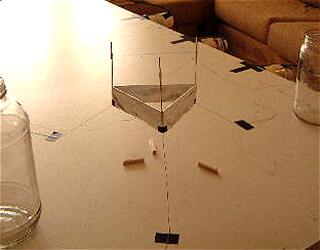
In this device there are no balsa wood cross members on the bottom of the foils. This is the same way that my lifter 1a was built. Also, the top edge of each foil is wrapped around its cross member and glued back onto itself. This means that there is no sharp foil edge that is on its own, thereby eliminating one source of leakage. To reduce leakage further, the foil is all one piece instead of being made of three individual pieces.
Another enhancement in this design is that the wire height is easily adjustable. At each vertex the wire is hot-glued to a small plastic cylinder. This cylinder, makes a snug fit with the supporting poles but is still easy to slide up and down.
|
|||||||||||
Last night I replicated the experiment and the results are very spectacular.I used version 1 of the lifter and is no doubt about the effect.

I did 2 tests:
1. regarding the change of polarity between wire and
aluminium foil and is a little but observing
diferrence...when (+) is attachet to the wire the
lifting force is biger.
2. ion wind test : by insulating the wire from the
foil with a plastic sheet.The lift is not affected by
this action.
I also agree to the ideea of tring some varied shapes
of the lifter to obtain the best configuration .
Best regards,
Cristian Marinescu
Return to the Lifters Builders page