3 September 2001. Thanks to BH.
This is Appendix B of
CJCSM 6231.05a
Manual for Employing Joint Tactical Communications - Joint Communications
Security, 2 November 1998.
[42 pages.]
FOR OFFICIAL USE ONLY
APPENDIX B
DETAILED COMSEC PROCEDURES
1. General. The procedures presented in this appendix are
for quick reference purposes only. They may amplify
information beyond the COMSEC manuals from which they were
derived. However, they are not intended to replace or
supersede the procedures in the manuals. The COMSEC manuals
take precedence in case of a discrepancy between these
procedures and the ones in the manuals. The procedures
include initializing a KG-83 and loading the ZKG, which is
then used to load the HGX-83 (along with analogous
procedures for initializing the KGX-93/93A, which does not
contain a ZKG); changing U-keys at DSVTs off AN/TTC-42s and
subordinate SB-3865s; point-to-point operation of DSVTs; and
OTAR of KG-84()s and KY-57s.
2. Initializing the KG-83 and Loading the Z-Key Generator
(ZKG). This paragraph provides procedures for initializing
the KG-83, loading the ZKG with the Z-key using a keying
device (AN/CYZ-10, KYK-13, KYX-15, or KOI-18), replacing a
Z-key using Command 91, and loading the Z-key into the
HGX-83. The procedures are written specifically for use at
an AN/TYC-39. The steps required at a CNCE are basically
the same. Additional information is added as applicable to
the AN/TTC-39(). Command 92 is used at AN/TTC-39()s for the
same purpose as Command 91. (Procedures for initializing
the KGX-93/93A are shown in parentheses.) The Z-key
functions with the ZKG and is used to encrypt and decrypt
keys when they are read into or out of the HUS. Zeroizing
the ZKG protects the contents of the HUS in an emergency. A
recovery from an alarm associated with a zeroized ZKG is
accomplished either by loading the ZKG with a new Z-key or
the original Z-key. Thus, if the HUS has been zeroized, as
would be the case at a cold start, each of the 1,024
locations would show a parity error when attempting to read
a key from the HUS. Therefore, an initial load Z during the
cold start procedures has the secondary effect of generating
1,024 new keys that will be used to load KG-82s and
associated KG-84()s for the local subscribers. Doctrine
does not permit storage of a used Z-key at the switch where
it was used. However, where operations requirements
dictate, a fill device containing the original Z-key may be
stored securely at a separate, nearby location.
a. Key Protection. If the Z-key is not available or
has been destroyed, the U- and X-keys stored in the HUS will
not be usable. To restart operation, a new set of keys must
be generated and stored in the HUS, and the KG-82s/KG-84()s
must be manually reloaded. Therefore, it is very important
that the Z-key be stored in a fill device with a new
battery, or the user may want to use hard-copy keying
material for this application. Changing the Z-key using
Command 91 will not destroy the keys stored in the HUS.
Each key stored in the HUS is sequentially decrypted in the
old Z-key and encrypted in the new Z-key.
b. Operational Concepts
(1) AN/TYC-39. In some deployments, the user may
want to consider loading the HUS with operational keys (U
and X) before shipping the AN/TYC-39. When the HUS is
loaded with keys, the AN/TYC-39 acquires the classification
of the messages that must be protected. In this case, the
classification of the AN/TYC-39 would be TOP SECRET and
would require TOP SECRET protection during shipment.
However, the HUS can be loaded before deployment, and the
ZKG can be zeroized. This protects the contents of the HUS
and lowers the security control level of the AN/TYC-39 from
TOP SECRET to CONFIDENTIAL if the KG-83 and Z-key keying
device are removed from the AN/TYC-39 and shipped
separately. In this situation, the AN/TYC-39 must be
protected only at the CONFIDENTIAL level during shipment.
To maintain the TOP SECRET level, the KG-83 and Z-key keying
device must be protected at the TOP SECRET level during
shipment.
(2) AN/TTC-39(). Unlike the configuration for the
message switch that has only one HGX-83 and operates
offline, the HGX-83s operating within the circuit switch
function in conjunction with the switch processor. For
circuit switch operation, the HGF-82 or HGF-85 is configured
with two HGX-83s. One of the HGX-83s is online with the
processor while the other HGX-83 operates in a standby mode.
After completion of the Command 89 diagnostic routines on
both HGX-83s, one HGX-83 must be assigned to the online
mode, and the other HGX-83 is assigned to the standby mode.
Thus, when operating with the AN/TTC-39 series, the HGX-83
operates in three states: online, standby, and offline.
When an HGX-83 is offline, the switch processor commands
will not affect it. The offline mode is used for
diagnostics and maintenance. Therefore, when starting the
COMSEC equipment from a cold start, the first step is to
initialize the KG-83s. The second step is to perform
diagnostics on the HGX-83s offline. The third step is to
load the ZKGs with a fill device (online and standby). The
final step is to load the COMSEC ID with keys. To enter
either the offline, standby, or online states for the HGX-
83s, an AOD-93, HGX-83 SWITCHOVER COMMAND must be used.
When starting the equipment from a cold start, assign one
HGX-83 to the online mode; assign the other HGX-83 to the
standby mode. Any write command to the HUS of an online
HGX-83, whether initiated manually or by the CS processor,
will cause identical information to be written into the
corresponding HUS location in the standby HGX-83. However,
a write command to the HUS of a standby HGX-83 will not
affect the HUS of the online HGX-83. At the end of the
Z-key cryptoperiod, use Command 92 to change the Z-key on
the Z-key generators of the HGX-83s used in a redundant
circuit switch configuration. New Z-keys must be loaded
into the HGX-83 from a fill device, regardless of origin.
Each key stored in the online HUS and COMSEC ID is
sequentially decrypted in the old Z-key, transferred to the
standby HGX-83, encrypted in the new Z-key, and written into
the equivalent standby HUS and COMSEC ID location. The
KYK-13 fill device used for the initial Z-key load
procedures can be used during this procedure. It is
recommended that the same fill device be used for this
application and the old Z-key be retained until the new
Z-key is successfully loaded.
c. Initialize KG-83. Initializing a KG-83 consists of
operating the ALARM and RANDOM push buttons on the front
panel in the proper sequence and observing the associated
indicators for proper displays. If the KG-83 push buttons
are not operated in the proper sequence, initialization will
not be successful. If a push button is operated out of
order, the entire procedure must be repeated. (To
initialize the KGX-93/93A, the ALARM and RANDOM push buttons
are depressed in the same sequence as that listed below,
after the POWER circuit breaker has been turned on.)
(1) Depress the ALARM push button.
(2) Observe that the ALARM and START indicators
remain illuminated after the push button is released. (The
ONLINE indicator remains illuminated if the KG-83 is
online.) For the AN/TYC-39 application, the KG-83 is not
operated online. After a brief interval, observe that the
ALARM indicator is extinguished and the RANDOM indicator is
illuminated. There is an interval timeout that delays an
indicator's illumination. If the next push button in
sequence is operated before the indicator responds to the
push button just released, no action will occur and the
button will have to be operated again. Unless otherwise
indicated, the START indicator will remain illuminated for
the rest of the procedure.
(3) Depress the RANDOM push button.
(4) Observe that the ONLINE indicator illuminates.
After a brief delay, observe that the RANDOM indicator is
extinguished and the ALARM indicator illuminates. The
ONLINE indicator will also extinguish.
(5) Depress the ALARM push button.
(6) After a brief delay, observe that the ALARM
indicator is extinguished and the RANDOM indicator is
illuminated.
(7) Depress the RANDOM push button.
(8) Observe that the ONLINE indicator illuminates.
After a brief delay, observe that the RANDOM and START
indicators are extinguished and the ALARM indicator is
illuminated. The ONLINE indicator will also extinguish.
(9) Depress the ALARM push button.
(10) Observe that the ALARM indicator remains
illuminated, and after a brief delay the START indicator is
illuminated.
(11) Depress the ALARM push button.
(12) Observe that the ALARM and START indicators
remain illuminated after the push button is released. After
a brief interval, observe that the ALARM indicator is
extinguished and the RANDOM indicator is illuminated.
(13) Depress the RANDOM push button.
(14) Observe that the ONLINE indicator illuminates.
After a brief delay, observe that the RANDOM indicator is
extinguished and the ALARM indicator is illuminated. The
ONLINE indicator will also extinguish.
(15) Depress the ALARM push button.
(16) After a brief delay, observe that the ALARM
indicator is extinguished and the RANDOM indicator is
illuminated.
(17) Depress the RANDOM push button.
(18) After a brief delay, observe that the RANDOM
and START indicators are extinguished and that the ALARM
indicator remains extinguished. The ONLINE indicator will
be extinguished if the KG-83 is offline. If the ALARM
indicator illuminates, repeat the initialization procedures,
steps (1) through (18).
d. HGX-83 Initialization. These procedures set up the
HGX-83 associated with the setup of a cold AN/TYC-39 message
switch or in which the ZKG has been zeroized and the current
Z-key is not available. (In an AN/TTC-39(), procedures are
basically the same, but Command 92 is used instead of
Command 91 in steps (20) and (22), below.) At the
completion of the "change Z-key" operation, all 1,024
locations in the HUS will contain valid keys. The Z-key can
be obtained from hard-copy keying material or generated by
the KG-83. To reduce the number of tapes required to
support an exercise, the KG-83 will be used to generate the
Z-key, and the KYK-13 fill device will be used to load the
ZKG. It is recommended that only the Z-key be stored in
this fill device and care should be taken that the fill
device is not inadvertently zeroized during the Z-key
cryptoperiod.
(1) Verify that the associated KG-83 has been
initialized and is operating without an ALARM condition.
(2) Turn the KYK-13 ADDRESS SELECT switch to the Z
ALL position.
(3) Hold the MODE switch in the Z position.
(4) Press and release the INITIATE button.
(5) Move the MODE switch to the OFF/CHECK position.
(6) Turn the ADDRESS SELECT switch to storage
register #1.
(7) Press and release the INITIATE button.
(8) If the INDICATOR light does not illuminate,
zeroizing was successful.
(9) Repeat steps (6) through (8) for the remaining
storage registers.
(10) Connect the KYK-13 directly to the KG-83 FILL
connector.
(11) Turn the KYK-13 MODE switch to ON.
(12) Turn the KYK-13 ADDRESS SELECT switch to
storage register #1.
(13) Press and release the KYK-13 INITIATE button.
(14) Monitor the KYK-13 INDICATOR light for a
momentary flash. A momentary flash of the INDICATOR light
would indicate that the KG-83 has sent a key with a good
parity to the KYK-13. Record in the management log (Z-key).
(15) Open, close, and open the code changer
compartment on the HGX-83 and connect the KYK-13 to the FILL
connector.
(16) Depress the button on the HGX-83 CODE CHANGER
next to the FILL connector.
(17) Verify that the INDICATOR light on the KYK-13
flashes. Remove the fill device from the HGX-83 FILL
connector.
(18) Close the CODE CHANGER door.
(19) If the Z-key was successfully loaded, the
CRYPTO and the Z ZERO lights will go out. If the Z-key was
not successfully loaded, the CRYPTO light remains
illuminated. If this occurs, repeat steps (15) through
(18).
(20) Set the MANUAL MODE COMMAND/ADDRESS switches
on the HGX-83 to 0091 and the MANUAL MODE FUNCTION switch to
CMD.
(21) Push the START push button.
(22) Verify that the MANUAL MODE CMD NO light
illuminates and that the MANUAL MODE DISPLAY indicates "91."
(23) Open the CODE CHANGER door. The Z ZERO and
the CRYPTO ALARM lights will illuminate. Close the CODE
CHANGER door and then reopen the CODE CHANGER door.
(24) Again, connect the KYK-13 with the Z-key to
the FILL connector on the front panel of the HGX-83. This
is the second time that the same Z-key is loaded into the
HGX-83 (KYK-13, register #1).
(25) Depress the button on the HGX-83 CODE CHANGER.
(26) Verify that the INDICATOR light on the KYK-13
flashes. Remove the fill device from the HGX-83 FILL
connector.
(27) Close the CODE CHANGER door.
(28) If the Z-key is successfully loaded, the
CRYPTO and Z ZERO lights extinguish. If the
Z-key was not successfully loaded, the MANUAL MODE ERROR
light will illuminate and the CRYPTO light remains
illuminated. Repeat steps (20) through (27).
(29) If the Z-key is successfully loaded, the HUS
ON will illuminate and remain on, and the CRYPTO light will
flash for 20 seconds. The MANUAL MODE DISPLAY and the
MANUAL MODE CMD NO. lights should extinguish, indicating a
successful operation. As a result of this operation, all
1,024 locations on the HUS now contain valid keys. At the
completion of step (28), perform a Command 89 (diagnostic
routine). (For the KGX-93/93A, perform a Command 87, a
simple diagnostic, or Command 89, a comprehensive
diagnostic, after the completed sequence described in
subparagraph 2c. This will complete the initialization of
the KGX-93/93A.)
(30) Set the MANUAL MODE COMMAND/ADDRESS switches
on the HGX-83 to 0089 and the MANUAL MODE FUNCTION switch to
CMD.
(31) Push the START button.
(32) Verify that the MANUAL MDE CMD NO. light
illuminates and that the MANUAL MODE DISPLAY indicates "89."
The HUS ON light should remain illuminated, and the ALARM
CRYPTO light will flash. If an error is detected, the
MANUAL MODE ERROR light will illuminate, and the MANUAL MODE
DISPLAY will display a particular error number to indicate
the place within the diagnostic subroutine where the failure
was detected. If error number 110311 is displayed, check
the Z-key, steps (33) through (36). If no error indication
is given, the HGX-83 is now operational.
(33) Set the MODE switch on the KYK-13 to the
OFF/CHECK position.
(34) Turn the ADDRESS SELECT switch to storage
register #1.
(35) Depress the MODE INITIATE button.
(36) Monitor the KYK-13 INDICATOR light for a
momentary flash. A momentary flash indicates that register
#1 contains a good parity. If the parity check fails,
repeat steps (1) through (32).
e. Change Z-Key. These procedures are used when the
Z-key must be changed at the end of the Z-key cryptoperiod
(3 months). The KYK-13 fill device used for the initial
Z-key load procedures can be used during these procedures.
It is recommended that the same fill device be used for this
application, and the old Z-key be retained until the new
Z-key is successfully loaded. After the new Z-key is
successfully loaded, Command 91 (in an AN/TTC-39(), use
Command 92 in steps (6), (8), and (15), below) decrypts the
U- and X-keys stored in the HUS with the old Z-key and
encrypts these keys with the new Z-key. At the completion
of Command 91, all U- and X-keys are encrypted with the new
Z-key and stored back in the same location of the HUS as
recorded in the management log.
(1) Connect the KYK-13 to the KG-83 FILL connector.
(2) Turn the KYK-13 MODE switch to the ON position.
(3) Turn the KYK-13 ADDRESS SELECT switch to
storage register #2 (storage register #1 contains the old
Z-key).
(4) Press and release the KYK-13 INITIATE button.
(5) Monitor the KYK-13 INDICATOR light for a
momentary flash. A momentary flash of the INDICATOR lamp
shows that the KG-83 has sent a key with a good parity.
Record in the management log.
(6) Set the MANUAL MODE COMMAND/ADDRESS switches on
the HGX-83 to 0091 and the MANUAL MODE FUNCTION switch to
CMD.
(7) Push the START button.
(8) Verify that the MANUAL MODE CMD NO. light
illuminates and that the MANUAL MODE DISPLAY indicates "91."
(9) Connect the KYK-13 to the FILL connector on the
front panel of the HGX-83.
(10) Open the CODE CHANGER cover door. The Z ZERO
and CRYPTO alarm lights will illuminate. Close the CODE
CHANGER cover door and then reopen the CODE CHANGER door.
(11) Depress the button on the HGX-83 CODE CHANGER.
(12) Verify that the INDICATOR light on the KYK-13
flashes. Remove the fill device from the HGX-83 FILL
connector.
(13) Close the CODE CHANGER door.
(14) If the Z-key is successfully loaded, the HUS
ON light will illuminate and remain on, and the CRYPTO light
will flash for 20 seconds. The MANUAL MODE DISPLAY and
MANUAL MODE CMD NO. lights should extinguish, indicating a
successful Command 91 operation.
(15) If the Z-key is successfully loaded, the Z
ZERO and CRYPTO lights will extinguish. If the Z-key is not
successfully loaded, the MANUAL MODE ERROR light will
illuminate and the CRYPTO light will remain on. If the
MANUAL MODE ERROR and CRYPTO lights remain illuminated,
repeat steps (9) through (13).
(16) Turn the KYK-13 ADDRESS SELECT switch to
storage register #1.
(17) Turn the KYK-13 MODE switch to Z (ZEROIZE).
While holding it in this position, press and release the
INITIATE button.
(18) Turn the KYK-13 MODE switch to OFF/CHECK, and
press and release the INITIATE button. The KYK-13 INDICATOR
light should not flash, verifying that storage register #1
has been zeroized. Record in the management log (Z-key
register #1 zeroized).
3. Changing U-Keys for AN/TTC-42 Subscribers
a. CPS Subscribers. U-keys are manually changed every
90 days. These changes do not require any database changes
by the switch operator. Restart of the U key should
coincide with projected low-traffic periods. These keys
must be unique per subscriber.
(1) Within 24 hours of scheduled restart, the
switch operator generates new U-keys for the directly
connected DSVTs using Command 27 at the AKDC and stores them
in appropriate fill devices.
(2) If external keys are to be used (requiring the
use of Index (IDX) 115 (External Variables)), the switch
operator fills the fill device from the AKDC spare locations
where external keys are stored.
(3) At the scheduled restart time, the fill devices
are distributed by appropriate personnel (wire personnel) to
assigned terminals.
(4) From the DSVT to be loaded, the wire person
calls the switch operator to report the directory number of
the terminal.
(5) The switch operator stays on the line and loads
the new U-key into the same AKDC location assigned to the
DSVT's RKID. Either a fill device can be used or Command 55
can be used if filling from AKDC external variable storage
(IDX 115). The switch operator tells the wire person to
hang-up and load the new U, take the DSVT offhook, and wait
for a dial tone. The switch operator then annotates the
rekey management forms. The REENTRY key is not required for
loading, provided that nothing has been done to the key
already residing in the X location of the DSVT. If the wire
person does not receive a dial tone, the REENTRY and U-key
must be loaded and a complete reentry procedure attempted.
(6) Dial tone indicates that supersession was
correct.
(7) The wire person proceeds to the next DSVT and
repeats steps (4) through (6).
(8) When all DSVTs have been loaded, all fill
devices are returned.
(9) The switch operator then uses Command 85 to
generate a new U-key and stores it in external variable
storage using IDX 115.
b. CSS Subscribers. These keys may be shared by all
subscribers. The cryptoperiod is 30 days. Up to nine RKIDs
may be assigned to one SB-3865. Generally, all switches are
assigned an RKID of 01. For each switch, a different UVS
location is assigned. However, to facilitate key change, a
minimum of three RKIDs should be assigned to each CSS at the
parent switch. For example, at switch 9202 RKIDs 01, 02,
and 03 are assigned to CSS 9220 with UVS locations assigned
301, 302, and 303, respectively; for switch 9230 RKIDs 01,
02, and 03 are assigned to UVS locations 304, 305, and 306,
respectively.
(1) All CSS DSVTs initialize in RKID 01.
(2) The CPS switch operator downloads all U-keys in
fill devices and provides them to CSS operators before cold
start.
(3) The CSS operator downloads the U-key for RKID
02 in fill devices and distributes with wire personnel.
(4) The wire person arrives at the DSVT to be
loaded and calls the CSS operator to identify the terminal
by directory number.
(5) The CSS operator performs IDX 2321, Add/Change
Loop Assignments, to change RKID from 001 to 002 for that
terminal. The CSS operator tells the other end to hang up
and load the new U-key.
(6) The wire person loads the U key and places a
91-call to the CSS operator. This verifies that the key
change was correct. The CSS operator annotates the REKEY
management form and instructs the wire person to proceed to
the next terminal.
(7) The wire person performs steps (4) through (6)
at each terminal to be loaded.
(8) When all DSVTs have been changed to RKID 002,
CSS operator informs CPS operator.
(9) The CPS operator overwrites the storage
locations assigned to RKID 01. Manual loading or Command 55
can be used.
(10) This procedure is repeated for RKID 03 and
back to RKID 01.
4. Point-to-Point Operation (DSVT-to-DSVT). The DSVT can
be operated point-to-point with another DSVT without the CS.
This operation is called the sole user mode and the DSVT
must be internally strapped for Mode II. An internal jumper
is provided on the Control Logic (E-EUL) PWA for this
function. For Mode II operation the jumper must be
connected between jacks A4J2 and A4J3. In the sole user
encrypted mode of operation, two DSVTs are connected
back-to-back via transmission equipment. Both keyboards are
disabled and signaling is accomplished automatically. When
the calling DSVT goes offhook, the called DSVT rings.
Secure operation can begin when the called DSVT goes
offhook. The sole user mode of operation does not provide a
plain text mode. When the DSVTs are operated in the sole
user mode, the cryptoperiod for the U- and X-key is the same
as that for a subscriber connected to the CSS. For the
U-key, the cryptoperiod is 1 month or the length of the
mission, whichever is less, and for the X-key it is 1 week
or the length of the mission, whichever is less. However,
the DSVTs can be rekeyed to change the X-key, which is
called Remote Cooperative Rekeying. Another DSVT feature is
the capability to manually send a new key from one end of
the DSVT link to the distant link using a KYX-15/DSVT
combination. This is called Manual Cooperative Variable
Transfer and can be applied to switched or nonswitched DSVTs
after secure end-to-end communications is established. To
support missions up to approximately 3 months, only the
rekeying feature is needed; the key transfer will not be
used for this application.
a. Point-to-Point Concept. The DSVTs can be configured
for point-to-point operation via wirelines or wideband radio
links and can be used for secure voice application, secure
voice orderwires, and S-key operation for discussing TOP
SECRET/SCI information. The user requirements dictate the
classification of the keys, where the keys are generated
(circuit switch or message switch), or if hard-copy keying
material is needed. The length of the mission determines if
the rekeying function will be used and may dictate how the
DSVT will be loaded. In all applications, both the U- and
the X-register of the DSVT must be loaded with keys. If the
length of the mission is longer than 1 week, the X-key must
be changed at the end of the 1-week cryptoperiod by using
the rekeying feature. When using the rekeying feature or
key transfer, U- and X-keys are needed for this application,
and the DSVTs to be rekeyed must have the same X-key. The
U-key must be held in the KYX-15 fill device at the
initiating DSVT for the rekeying operation. The KYX-15 is
the only fill device capable of performing this rekeying.
b. Key Generation. When a key is used for TOP
SECRET/SCI operation in the sole user mode, the operation is
identical to the X-key operation, except that the key must
be generated by the AN/TYC-39 or paper tape. The X-key for
TOP SECRET/SCI operation will be loaded into the X-register,
and the keying material must be protected at the TOP
SECRET/SCI level. TOP SECRET X-keys are not required when
the S-key is used.
c. Rekeying Rules. For missions longer than 1 week
that use the rekeying feature, the fill device must be the
KYX-15. When loading the KYX-15, load the new X-key into
one storage register followed by storage location containing
the U-key of the receiving DSVT. For example, if register
#1 contains the new X-key, register #2 or higher must
contain the U-key. If using the rekeying function, only the
DSVT initiating the key change will need the KYX-15. The
receiving DSVT can be initialized with the U- and X-keys
using a KYK-13. If using paper tape, select the KOI-18 tape
reader as the fill device. Again, when loading the U-key
into the KYX-15, be sure the U-key is the same one
identified for the receiving DSVT. This key will be used
during a rekeying operation.
d. Point-to-Point Scenarios. For point-to-point
operation, three scenarios will be outlined. The first
scenario will support a 7-day mission; the second scenario
will support a mission up to 30 days; and a third scenario
will last up to 90 days.
(1) Point-to-Point Operation - 1 Week
(DSVT-to-DSVT). When the DSVTs are deployed point-to-point
for 1 week or less, two keys are needed to support the
operation. Again, it is assumed that the operation is
certified for SECRET usage and the CS KG-83 will be used to
generate the U- and X-keys. If the classification of the
mission is TOP SECRET or TOP SECRET/SCI, then the AN/TYC-39
KG-83 must be used to generate the key or hard-copy key
material must be used. This application uses two KYK-13s.
The second KYK-13 will be loaded by the first KYK-13, which
was loaded directly from the KG-83.
(a) Load First KYK-13
1. Turn the KYK-13 ADDRESS SELECT switch
to register #1.
2. Turn the KYK-13 MODE switch to Z
(zeroize), and while holding it in this position, press and
release the INITIATE button.
3. Turn the KYK-13 MODE switch to the
OFF/CK position; press and release the INITIATE button. The
KYK-13 INDICATOR light should not flash, thus verifying that
the selected storage register has been zeroized.
4. Connect the KYK-13 to the AN/TTC-39()
KG-83 OUTPUT connector.
5. Turn the KYK-13 MODE switch to the ON
position.
6. Press and release the KYK-13 INITIATE
button.
7. Monitor the KYK-13 INDICATOR light for
a momentary flash. A momentary flash of the INDICATOR light
would show that the KG-83 has sent a key with a good parity
to the KYK-13. Record on KYK-13 and in the management log
(U-key for point-to-point operation). Repeat steps 1
through 7 for the X-key using register #2. Remove the
KYK-13 from the KG-83 OUTPUT connector.
(b) Load Second KYK-13
1. Check that storage register #1 on the
KYK-13 has been zeroized, steps 4d(1)(a)1 through 4d(1)(a)3.
2. Connect the KYK-13 (second) directly
to the KYK-13 with the U- and X-keys.
3. Turn the KYK-13 (second) MODE switch
to the ON position.
4. Turn the KYK-13 (second) ADDRESS
SELECT switch to storage register #1.
5. Turn the KYK-13 (first) MODE switch to
the ON position. This is the KYK-13 with the U-key stored
in register #1.
6. Turn the KYK-13 (first) ADDRESS SELECT
switch to storage register #1.
7. Press and release the INITIATE button
on the KYK-13 to be filled.
8. Both KYK-13 INDICATOR lights will give
a momentary flash to indicate a key transfer with a good
parity. Record on KYK-13 and in the management log (U-key
for point-to-point operation). Repeat the above steps 4, 6,
7, and 8 for the X-key (register #2).
9. Turn both KYK-13 MODE switches to the
OFF/CK position and disconnect the KYK-13.
(c) Load DSVTs with U- and X-keys. During
the load procedure, the DSVT must remain onhook.
1. On the DSVT, move the VAR STORAGE
switch to the NORM position.
2. Set the DSVT FUNCTION SEL switch to
the DSBL position momentarily, and then move to the LDU
position.
3. Connect the KYK-13 to the FILL
connector on the DSVT.
4. Turn the ADDRESS SELECT switch to
position #1.
5. Turn the MODE switch to the ON
position.
6. Momentarily set the VAR STORAGE switch
on the DSVT to the LOAD position until a half-second tone is
heard; then release the control. If another half-second
tone is heard, the U-register has been properly loaded with
the U-key. If a 10-second tone is heard, the key was not
accepted by the DSVT due to bad parity. If no tone is
heard, the key transfer was incomplete. In both cases,
momentarily move the FUNCTION SEL switch to the DSBL
position, and then return the FUNCTION SEL switch to the LDU
position and repeat this step.
7. Turn the ADDRESS SELECT switch to
position #2.
8. Set the DSVT FUNCTION SEL switch to
the LDX position and repeat step 6.
9. Upon completion of the load operation,
turn the FUNCTION SEL switch to the OP position.
10. On the KYK-13, move the MODE switch
to the OFF/CK position and remove the fill device from the
DSVT.
11. The DSVTs are now ready for secure
operation. If the transmission link is operational, either
DSVT can go offhook and the distant DSVT will ring.
(2) Point-to-Point Operation up to 30 Days
(DSVT-to-DSVT). Missions lasting over 1 week and up to 30
days will require the U-key plus an X-sync key and the
traffic keys. These keys must be loaded into two fill
devices. The first fill device, the KYX-15, will be loaded
directly from the AN/TTC-39 series KG-83 and retained at the
DSVT location, initiating the key change. The second fill
device, the KYK-13, will be loaded from the KYX-15 and
deployed with the remote DSVT. In addition, the KYX-15 will
be loaded with three additional X-traffic keys to replace
traffic keys at the completion of the cryptoperiod(s). For
a fail-safe mode of operation, an X-sync key will be loaded
and retained in the KYX-15 and KYK-13. Thus, if problems
develop during the second, third, or fourth week of the
mission (zeroized DSVT, fail to synchronize), the remote
DSVT will always retain the X-sync key. Therefore, at the
start of the 30-day mission, the KYX-15 will be loaded with
an X-sync, four X-traffic keys, and the U-rekeying key. For
ease of management, register #1 will contain the X-sync key,
register #2 (X-key for the first week of operation),
register #3 (X-key for the second week of operation),
register #4 (X-key for the third week of operation),
register #5 (X-key for the fourth week of operation) and,
finally, register #6 (the U-key). The X-key(s) must be
loaded in lower numbered registers and the U-keys in higher
numbered registers to observe the rules for the KYX-15
during the rekeying operation. A second approach is
available that does not use rekeying. This approach
requires loading the same X-traffic keys into two fill
devices. Operating procedures would be the same as for
1 week of operation except that a new X-traffic key would be
loaded at the end of the 1-week cryptoperiod.
(a) Load KYX-15 for the Initiating DSVT. This
scenario presumes the DSVTs support only SECRET traffic.
Thus, the CS KG-83 must be used to generate the U- and X-
keys. If the classification of the mission is TOP SECRET or
TOP SECRET/SCI, the AN/TYC-39 KG-83 must be used to generate
the keys. The procedures listed below will support missions
that will last longer than 1 week, and the X-traffic key
must be changed at the end of the 1-week cryptoperiod.
1. Check all the storage registers on the
KYX-15 to see if they have been zeroized. If not, follow
the procedures Outlined below in steps 2 through 7.
2. Move the KYX-15 MODE switch to the Z
ALL position.
3. Press and release the INITIATE button.
4. Move the KYX-15 MODE switch to the
OFF/CK position.
5. Turn the ADDRESS SELECT switch #1 to
the ON position.
6. Press and release the INITIATE button.
7. If the INDICATOR LIGHT does not
illuminate, zeroize was successful. Turn ADDRESS select
switch #1 to the OFF position. Repeat steps 5, 6, and 7 for
all storage registers.
8. Connect the KYX-15 to the CS KG-83
OUTPUT connector via fill cable.
9. Move the ADDRESS SELECT switch for
register #1 to the ON position.
10. Set the KYX-15 MODE switch to the LD
position.
11. Momentarily push the KYX-15 INITIATE
button.
12. Observe that the PARITY indicator on
the KYX-15 flashes to indicate a good parity during the load
operation.
13. Record on the KYX-15 and in the
management log (X-sync key for point-to-point operation).
14. Set the ADDRESS SELECT switch #1 to
the OFF position.
15. Repeat steps 9, 11, 12, and 14 for
registers #2, 3, 4, 5, and 6.
16. Set the KYX-15 MODE switch to the
OFF/CK position. Disconnect the fill device from the KG-83.
17. Record on KYX-15 and in the
management log.
a. Register #2 (X-traffic key for
week 1).
b. Register #3 (X-traffic key for
week 2).
c. Register #4 (X-traffic key for
week 3).
d. Register #5 (X-traffic key for
week 4).
e. Register #6 (U-key for 1 month of
operation).
(b) Load KYK-13 from the KYX-15 for the Remote
DSVT
1. Check storage registers #1, #2, and #3
on the KYK-13 for a zeroized condition.
2. Turn the KYK-13 ADDRESS SELECT switch
to register #1.
3. Turn the KYK-13 MODE switch to the
OFF/CHECK position; press and release the INITIATE button.
The KYK-13 INDICATOR light should not flash, thus verifying
that the selected storage register has been zeroized.
Repeat steps 1, 2, and 3 for register #2 and #3.
4. To avoid a false fill, make sure that
both MODE switches on the fill devices are in the OFF/CK
position.
5. Connect the KYK-13 to the KYX-15
directly or with a fill cable.
6. Turn the KYK-13 MODE switch to ON, and
set the ADDRESS SELECT switch to register #1.
7. On the KYX-15, set ADDRESS SELECT
switch #1 (X-sync key) to the ON position. (All other
switches must be in the OFF position.)
8. Turn the KYX-15 MODE switch to the LD
position.
9. Press and release the KYK-13 INITIATE
button. Do not press the KYX-15 INITIATE button.
10. Verify that the KYK-13 and KYX-15
INDICATOR lights momentarily flash, which indicate that the
KYX-15 has transferred a key with a good parity to the
KYK-13.
11. Return the KYX-15 ADDRESS SELECT
switch #1 to the OFF position.
12. Turn the KYK-13 MODE switch to the
OFF/CHECK position.
13. Press and release the KYK-13 INITIATE
button.
14. Verify that the INDICATOR light
flashes, which indicates that the X-sync key has been
stored.
15. Record on the KYK-13 and in the
management log (X-sync key for point-to-point operation).
16. Repeat steps 6 through 15 for the
X-key (week 1) and the U-key. Storage register #2 in the
KYX-15 contains the X-traffic key for week 1, and storage
register #6 contains the U-rekeying key. Store the
X-traffic key in register #2 and the U-key in register #3 in
the KYK-13.
17. Ensure the KYK-13 MODE switch is in
the OFF/CK position and return the ADDRESS SELECT switch to
the OFF position.
18. Turn the KYX-15 MODE switch to the
OFF/CHECK position.
19. Disconnect the KYK-13 from the
KYX-15.
(c) Load the Initiating DSVT (KYX-15). The
DSVT must remain onhook during load procedures.
1. On the DSVT, move the VAR STORAGE
switch to the NORM position.
2. Set the DSVT FUNCTION SEL switch to
the DSBL position momentarily and then move to the LDU
position.
3. Connect the KYX-15 with its
interconnecting cable to the FILL connector on the DSVT.
4. Turn the ADDRESS SELECT switch #6 to
the ON position (U-key), and set the MODE switch to the ON
position.
5. Set the VAR STORAGE switch on the DSVT
to the LOAD position until you hear a half-second tone; then
release the control. If another half-second tone is heard,
the U-key has been properly loaded into the DSVT. If a
10-second tone is heard, the U-key was not accepted by the
DSVT due to bad parity. If no tone is heard, the key
transfer was incomplete. In both cases, momentarily move
the FUNCTION SEL switch to the DSBL position, and then
return the FUNCTION SEL switch to the LDU position and
repeat step 5.
6. Return ADDRESS SELECT switch #6 to the
OFF position.
7. Set the DSVT FUNCTION SEL switch to
the LDX position.
8. Turn ADDRESS SELECT switch #2 to the
ON position.
9. Set the VAR STORAGE switch on the DSVT
to the LOAD position until you hear a half-second tone; then
release the control. If another half-second tone is heard,
the X-traffic key has been properly loaded into the DSVT.
If a 10-second tone is heard, the X-traffic key was not
accepted by the DSVT. If no tone is heard, the key transfer
was incomplete. In both cases, momentarily move the
FUNCTION SEL switch to the DSBL position, and then return
the FUNCTION SEL switch to the LDX position and repeat
step 9.
10. Upon completion of the load
operation, turn the FUNCTION SEL switch to the OP position
on the DSVT.
11. On the KYX-15, turn ADDRESS SELECT
switch #2 to the OFF position.
12. On the KYX-15, turn the MODE switch
to the OFF/CK position and remove the interconnecting cable
from the DSVT.
(d) Load the Remote DSVT (KYK-13). The DSVT
must remain onhook during load procedures.
1. On the DSVT, move the VAR STORAGE
switch to the NORM position.
2. Momentarily set the DSVT FUNCTION SEL
switch to the DSBL position and then move to the LDU
position.
3. Connect the KYK-13 with its inter-
connecting cable to the FILL connector on the DSVT.
4. Turn the ADDRESS SELECT switch to
position #3 (U-key) and set the MODE switch to the ON
position.
5. Set the VAR STORAGE switch on the DSVT
to the LOAD position until you hear a half-second tone; then
release the control. If another half-second tone is heard,
the U-key has been properly loaded into the DSVT. If a
10-second tone is heard, the V-key was not accepted by the
DSVT due to bad parity. If no tone is heard, the key
transfer was incomplete. In both cases, momentarily move
the FUNCTION SEL switch to the DSBL position, and then
return the FUNCTION SEL switch to the LDU position and
repeat step 5.
6. Turn the ADDRESS SELECT switch to
position #2 (X-traffic key).
7. Set the DSVT FUNCTION SEL switch to
the LDX position.
8. Set the VAR STORAGE switch on the DSVT
to the LOAD position until you hear a half-second tone; then
release the control. If another half-second tone is heard,
the X-key has been properly loaded into the DSVT. If a
10-second tone is heard, the X-key was not accepted by the
DSVT. If no tone is heard, the key transfer was incomplete.
In both cases, momentarily move the FUNCTION SEL switch to
the DSBL position and then return the FUNCTION SEL switch to
the LDX position and repeat step 8.
9. Upon completion of the load operation,
turn the FUNCTION SEL switch to the OP position on the DSVT.
10. On the KYK-13, move the MODE switch
to the OFF/CK position and remove the interconnecting cable
from the DSVT.
11. The DSVTs are now ready for secure
operation. If the transmission link is operational, either
DSVT can go offhook and the distant DSVT will ring.
(e) Rekeying the Remote DSVT with a New
X-Traffic Key. At the end of the 1-week cryptoperiod, the
X-traffic key must be changed. The DSVT (INITIATOR) will
rekey the remote DSVT with the new X-traffic key. The
remote DSVT must contain the current X-key and the
U-rekeying key. The DSVTs must be in end-to-end commu-
nication. The DSVT initiating the key change requires a
KYX-15, which has the new X-traffic key in a storage
register followed by a storage register containing the
U-key. In this case, the X-sync key was stored in register
#1, and the new X-traffic key (week 2) is stored in register
#3. The U-key is stored in register #6.
1. Establish voice communications between
the DSVTs, and maintain communications during the rekeying
operation.
2. At the sending DSVT (INITIATOR),
connect the KYX-15 to the FILL connector using the
interconnecting cable.
3. Set the KYX-15 MODE switch to the AK
position.
4. Set ADDRESS SELECT switches #3 and #6
to the ON position (all other switches to the OFF position).
Register #3 is the new X-traffic key and register #6
contains the U-key.
5. Momentarily press the INITIATE button
to implement the key change operation.
6. Turn ADDRESS SELECT switch #6 to the
OFF position and the MODE switch to the LD position. Leave
ADDRESS SELECT switch #3 (new X-traffic key) in the ON
position.
7. Verify voice communications with the
distant end (new X-traffic key).
8. Place the INITIATING DSVT onhook.
When the INITIATING DSVT goes onhook, the new X-traffic key
is lost and must be loaded manually. However, this is only
for the INITIATING DSVT. The remote DSVT has been rekeyed
and contains the new X-traffic key.
9. Set the DSVT (INITIATOR) FUNCTION SEL
switch to the LDX position.
10. Set the VAR STORAGE switch on the
DSVT to the LOAD position until you hear a half-second tone;
then release the control. If another half-second tone is
heard, the new X-traffic key has been properly loaded into
the DSVT. If a 10-second tone is heard, the new X-traffic
key was not accepted by the DSVT. If no tone is heard, the
key transfer was incomplete. In both cases, momentarily
move the FUNCTION SEL switch to the DSBL position and return
the FUNCTION SEL switch to the LDX position and repeat
step 10.
11. Upon completion of the load-X
operation, turn the FUNCTION SEL switch to the OP position
and go offhook to verify communication with the remote DSVT.
12. On the KYX-15, turn ADDRESS SELECT
switch #3 to the OFF position. At this time the old
X-traffic key must be destroyed (zeroized) in both fill
devices. For the KYX-15, register #2 contains the X-traffic
key (week 1) and for the KYK-13, register #2 also contains
the X-traffic key for week 1.
13. On the KYX-15, turn the MODE switch
to the OFF/CK position and remove the interconnecting cable
from the DSVT.
14. Repeat steps 1 through 13 for each
new X-cryptoperiod. Register #4 contains the X-traffic key
for the third week of operation. Register #1 of the KYX-15
contains the X-sync key for fail-safe operation and can be
used to establish communications as outlined in steps (c)
and (d). After communications are established with the
X-sync key, the DSVT link must be rekeyed with the current
X-traffic key.
(3) Point-to-Point Operation up to 12 Weeks
(DSVT-to-DSVT). Missions lasting over 30 days and up to 12
weeks will require three U-keys plus the X-sync key at the
initiating and the remote DSVTs. In addition, the KYX-15 at
the initiating DSVT must contain the X-traffic keys to
support up to 90 days, which will be 12 X-traffic keys.
Therefore, the KYX-15 must be loaded with 12 X-traffic keys,
3 rekeying keys, and the X-sync key. The cryptoperiod for
the rekeying key U is 30 days. At the completion of the U
cryptoperiod, the U-key must be manually loaded at both ends
of the link. For a fail-safe mode of operation, the X-sync
key will be retained in the KYX-15 and the remote DSVT
location. At the start of the mission both DSVTs will be
loaded with the operational U-key and the X-sync key. When
communications are established between the two DSVTs, the
initiating DSVT must rekey the remote DSVT with the current
X-traffic key. If, during the mission, a reload becomes
necessary, both DSVTs must be manually loaded with the
current U-key and the X-sync key. When communications are
reestablished between the two DSVTs, the initiating DSVT
must rekey the remote DSVT with the current X-traffic key.
For ease of management, register #1 of the KYX-15 will
contain the X-sync key. An example of the KYX-15 to support
a 90-day mission is illustrated in Figure B-1. A SECRET
mission classification is assumed, so the CS KG-83 can be
used to generate the keys. Two fill devices will be needed.
The first fill device, the KYX-15, must be loaded directly
from the CS KG-83 and retained at the DSVT location
initiating the key change. The second fill device, the
KYK-13, will be loaded from the KYX-15 and then deployed
with the remote DSVT. The remote fill device (KYK-13)
requires only four keys, the X-sync key and three rekeying
keys. To satisfy the rekeying rules for the KYX-15, the
X-traffic keys must be stored in the lower numbered
registers and the U-keys in the higher numbered registers.
_______________________________________________
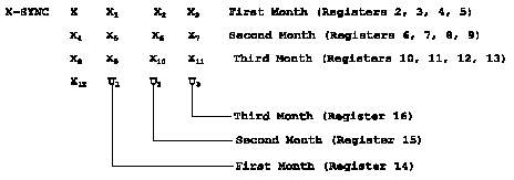 Figure B-1. KYX-15 Register Fill
_______________________________________________
(a) Load KYX-15 for Initiating DSVT. The
procedures listed below will support missions up to 12
weeks. The X-traffic key must be changed (rekeyed by
initiating DSVT) at the end of the 7-day cryptoperiod, and
the U-keying key must be manually changed at the end of the
30-day cryptoperiod.
1. Check all the storage registers on the
KYX-15 to see if they have been zeroized. If not, follow
the procedures outlined below in steps 2 through 7.
2. Move the KYX-15 MODE switch to the Z
ALL position.
3. Press and release the INITIATE button.
4. Move the KYX-15 MODE switch to the
OFF/CK position.
5. Turn the ADDRESS SELECT switch #1 to
the ON position.
6. Press and release the INITIATE button.
7. If the INDICATOR LIGHT does not
illuminate, zeroize was successful. Turn ADDRESS SELECT
switch #1 to the OFF position. Repeat steps 5, 6, and 7 for
all storage registers.
8. Connect the KYX-15 to the AN/TTC-39
KG-83 OUTPUT connector via fill cable.
9. Move the ADDRESS SELECT switch for
register #1 to the ON position.
10. Set the KYX-15 MODE switch to the LD
position.
11. Momentarily push the KYX-15 INITIATE
button.
12. Observe that the PARITY indicator on
the KYX-15 flashes to indicate a good parity during the load
operation.
13. Set the ADDRESS SELECT switch #1 to
the OFF position.
14. Repeat steps 9, 11, 12, and 13 for
registers #2, 3, 4, 5, 6, 7, 8, 9, 10, 11, 12, 13, 14, 15,
and 16.
15. Record on KYX-15 and in the
management log.
a. Register #1 (X-sync key).
b. Register #2 (X-traffic key for
week 1).
c. Register #3 (X-traffic key for
week 2).
d. Register #4 (X-traffic key for
week 3).
e. Register #5 (X-traffic key for
week 4).
f. Register #6 (X-traffic key for
week 5).
g. Register #7 (X-traffic key for
week 6).
h. Register #8 (X-traffic key for
week 7).
i. Register #9 (X-traffic key for
week 8).
j. Register #10 (X-traffic key for
week 9).
k. Register #11 (X-traffic key for
week 10).
l. Register #12 (X-traffic key for
week 11).
m. Register #13 (X-traffic key for
week 12).
n. Register #14 (U-key for month 1).
o. Register #15 (U-key for month 2).
p. Register #16 (U-key for month 3).
16. Set the KYX-15 MODE switch to the
OFF/CK position. Disconnect the fill device from the KG-83.
(b) Load KYK-13 from the KYX-15 for the Remote
DSVT
1. Check all storage registers on the
KYK-13 to see if they have been zeroized. If not, follow
procedures outlined below in steps 2 through 7 below.
2. Move the ADDRESS SELECT switch to the
Z ALL position.
3. Hold the MODE switch in the Z
position.
4. Momentarily depress the INITIATE
button.
5. Move the MODE switch to the OFF/CK
position.
6. Turn the KYK-13 ADDRESS SELECT switch
to register #1.
7. Momentarily press the INITIATE button.
The KYK-13 INDICATOR light should not flash, which verifies
that the selected storage register has been zeroized.
Repeat steps 6 and 7 for the remaining registers.
8. To avoid a false fill, make sure that
both MODE switches on the fill devices are in the OFF/CK
position.
9. Connect the KYK-13 to the KYX-15
either directly or with a fill cable.
10. Turn the KYK-13 MODE switch to the ON
position and set the ADDRESS SELECT switch to register #1.
11. On the KYX-15, set ADDRESS SELECT
switch #1 (X-sync key) to the ON position. All other
switches must be in the OFF position.
12. Turn the KYX-15 MODE switch to the LD
position.
13. Press and release the KYK-13 INITIATE
button. Do not press the KYX-15 INITIATE button.
14. Verify that the KYK-13 and KYX-15
INDICATOR lights momentarily flash, which indicates that the
KYX-15 has transferred a key with a good parity to the
KYK-13.
15. Return the KYX-15 ADDRESS SELECT
switch #1 to the OFF position.
16. Turn the KYK-13 MODE switch to the
OFF/CHECK position.
17. Press and release the KYK-13
INITIATE button.
18. Verify that the INDICATOR light
flashes, which indicates that the X-sync key has been
stored.
19. Record on the KYK-13 and in the
management log (X-sync key for point-to-point operation).
20. Repeat steps 10 through 19 for the
U-keys. The U-keys are stored in registers #14, 15, and 16
in the KYX-15. In the KYK-13, store the U-key for the first
month in register #2, the U-key for the second month in
register #3, and the U-key for the third month in
register #4.
21. Turn the KYX-15 MODE switch to the
OFF/CK position.
22. Turn the KYK-13 MODE switch to the
OFF/CHECK position.
23. Disconnect the KYK-13 from the
KYX-15.
(c) Load the Initiating DSVT (KYX-15). The
DSVT must remain onhook during the load procedure.
1. On the DSVT, move the VAR STORAGE
switch to the NORM position.
2. Momentarily set the DSVT FUNCTION SEL
switch to the DSBL position and then move to the LDU
position.
3. Connect the KYX-15 with its inter-
connecting cable to the FILL connector on the DSVT.
4. Turn ADDRESS SELECT switch #14 to the
ON position (U-key for the first month).
5. Set the MODE switch to the LD
position.
6. Set the VAR STORAGE switch on the
DSVT to the LOAD position until you hear a half-second tone;
then release the control. If another half-second tone is
heard, the U-key has been properly loaded into the DSVT. If
a 10 second tone is heard, the U-key was not accepted by the
DSVT because of bad parity. If no tone is heard, the key
transfer was incomplete. In both cases, momentarily move
the FUNCTION SEL switch to the DSBL position, and then
return the FUNCTION SEL switch to the LDU position and
repeat step 6.
7. Return ADDRESS SELECT switch #14 to
the OFF position.
8. Set the DSVT FUNCTION SEL switch to
the LDX position.
9. Turn ADDRESS SELECT switch #1 to the
ON position (X-sync key).
10. Repeat step 6 for the X-sync key.
11. Upon completion of the load
operation, turn the FUNCTION SEL switch to the OP position
on the DSVT.
12. On the KYX-15, turn ADDRESS SELECT
switch #1 to the OFF position.
13. On the KYX-15, turn the MODE switch
to the OFF/CK position and remove the interconnecting cable
from the DSVT.
(d) Load the Remote DSVT (KYK-13). The DSVT
must remain onhook during the load procedures.
1. On the DSVT, move the VAR STORAGE
switch to the NORM position.
2. Momentarily set the DSVT FUNCTION
switch to the DSBL position and then move to the LDU
position.
3. Connect the KYK-13 with its inter-
connecting cable to the FILL connector on the DSVT.
4. Turn the ADDRESS SELECT switch to
position #2 (U-key for the first month) and set the MODE
switch to the ON position.
5. Set the VAR STORAGE switch on the
DSVT to the LOAD position until you hear a half-second tone;
then release the control. If another half-second tone is
heard, the U-key has been properly loaded into the DSVT. If
a 10-second tone is heard, the U-key was not accepted by the
DSVT because of bad parity. If no tone is heard, the key
transfer was incomplete. In both cases, momentarily move
the FUNCTION SEL switch to the DSBL position and then return
the FUNCTION SEL switch to the LDU position and repeat
step 5.
6. Turn the ADDRESS SELECT switch to
position #1 (X-sync key).
7. Set the DSVT FUNCTION SEL switch to
the LDX position.
8. Repeat step 5 for the X-sync key.
9. Upon completion of the load
operation, turn the FUNCTION SEL switch to the OP position.
10. On the KYK-13, move the MODE switch
to the OFF/CK position and remove the interconnecting cable
from the DSVT.
11. The DSVTs are now ready for secure
operation. If the transmission link is operational, either
DSVT can go offhook and the distant DSVT will ring. When
communications are established between the two DSVTs, the
DSVTs must be rekeyed with the current X-traffic key.
(e) Rekeying the Remote DSVT with the
Current X-traffic Key. After communications have been
established in the X-sync key, the remote DSVT must be
rekeyed with the current X-traffic key. These procedures
are needed at the end of the 1-week cryptoperiod when the
X-traffic key must be changed. The DSVT (INITIATOR) will
rekey the remote DSVT with the new X-key.
1. Establish voice communications
between the DSVTs and maintain communications during the
rekeying operation.
2. At the sending DSVT (INITIATOR),
connect the KYX-15 to the FILL connector using the
interconnecting cable.
3. Set the KYX-15 MODE switch to the AK
position.
4. Set ADDRESS SELECT switch #2 and #14
to the ON position (all other switches to the OFF position).
Register #2 is the X-traffic key for week 1, and register
#14 contains the rekeying key (U) for month 1.
5. Momentarily press the INITIATE button
to implement the key change operation.
6. Turn ADDRESS SELECT switch #14 to the
OFF position and the MODE switch to the LD position. Leave
ADDRESS SELECT switch #2 (new X-traffic key for the first
week) in the ON position.
7. Verify voice communications with the
distant end (new X-traffic key).
8. Place the INITIATING DSVT onhook.
When the INITIATING DSVT goes onhook, the new X-traffic key
is lost and the X-sync key remains in the DSVT. Thus, the
new X-traffic key must be loaded manually. However, this is
only for the INITIATING DSVT. The remote DSVT contains the
new X-traffic key.
9. Set the DSVT (INITIATOR) FUNCTION SEL
switch to the LDX position.
10. Set the VAR STORAGE switch on the
DSVT to the LOAD position until you hear a half-second tone;
then release the control. If another half-second tone is
heard, the new X-key has been properly loaded into the DSVT.
If a 10-second tone is heard, the new X-key was not accepted
by the DSVT. If no tone is heard, the key transfer was
incomplete. In both cases, momentarily move the FUNCTION
SEL switch to the DSBL position and return the FUNCTION SEL
switch to the LDX position and repeat step 10.
11. Upon completion of the load-X
operation, turn the FUNCTION SEL switch to the OP position
and go offhook to verify communications with the remote
DSVT.
12. On the KYX-15, turn ADDRESS SELECT
switch #2 to the OFF position.
13. On the KYX-15, turn the MODE switch
to the OFF/CK position and remove the interconnecting cable
from the DSVT.
14. Repeat steps 1 through 13 at the
beginning of each new X-cryptoperiod. Register #3 contains
the X-traffic key for the second week of operation.
(f) Manually Change the U-Key. At the end
of the 30-day U-key cryptoperiod, the U-key must be manually
changed in both DSVTs. (Policy will not allow a rekeying
key to be electronically transferred.) At the initiating
DSVT, the U-key for month 2 of operation is in register #15
of the KYX-15. At the remote DSVT, the U-key is in register
#3 (month 2) of the KYK-13. After the new U-key is loaded
in both DSVTs, the link should be able to operate in the
current X-key. After communications have been established
between the DSVTs, the initiating DSVT must rekey the remote
DSVT with the new X-key (register #6 in the KYX-15 contains
the X for week 5). However, if communications cannot be
established between the DSVTs, both ends of the link may try
loading the X-sync key (register #1 in both fill devices) in
both DSVTs to establish communications. If successful, then
try again to rekey the remote DSVT with the new X-key. Note
that the DSVTs must remain onhook during the load
procedures.
1. On the DSVT (INITIATOR), move the VAR
STORAGE switch to the NORM position.
2. Set the MODE switch to the LDU
position.
3. Connect the KYX-15 with its
interconnecting cable to the FILL connector on the DSVT.
4. Turn ADDRESS SELECT switch #15 to the
ON position (U-key for the second month) and set the MODE
switch to the LD position.
5. Set the VAR STORAGE switch on the
DSVT to the LOAD position until you hear a half-second tone;
then release the control. If another half-second tone is
heard, the U-key has been properly loaded into the DSVT. If
a 10-second tone is heard, the U-key was not accepted by the
DSVT because of bad parity. If no tone is heard, the key
transfer was incomplete. In both cases, momentarily move
the FUNCTION SEL switch to the DSBL position, and then
return the FUNCTION SEL switch to the LDU position and
repeat step 5.
6. Return ADDRESS SELECT switch #15 to
the OFF position.
7. Turn the MODE switch to the OFF/CK
position and remove the interconnecting cable from the DSVT.
8. Turn the FUNCTION SEL switch to the
OP position.
9. On the remote DSVT, move the VAR
STORAGE switch to the NORM position.
10. Set the DSVT FUNCTION switch to the
LDU position.
11. Connect the KYK-13 with its
interconnecting cable to the FILL connector on the DSVT.
12. Turn the ADDRESS SELECT switch to
position #3 (U-key for the second month),and set the MODE
switch to the ON position.
13. Repeat step 5.
14. Upon completion of the load-U
operation, turn the FUNCTION SEL switch to the OP position.
15. On the KYK-13, move the MODE switch
to the OFF/CK position and remove the interconnecting cable
from the DSVTs.
16. The DSVTs are now ready for secure
operation. If the transmission link is operational, either
DSVT can go offhook and the distant DSVT will ring. If the
DSVTs do not synchronize, repeat the load procedures using
the new U-key and the X-sync key located in register #1 in
both fill devices. In both cases, the X-sync key must be
changed by the rekeying procedure, which will be initiated
by the DSVT (INITIATOR).
17. Repeat the steps in subparagraphs
4a(3)(e)1 through 4a(3)(e)13.
5. Over-The-Air Rekeying and Key Transfer. OTAR is the
process of electrically transmitting new TEK to the distant
end of a communications link, which is operated either
point-to-point or netted. Procedures will be presented for
rekeying nets secured by KG-84()s or VINSONs. KG-84()
procedures are included in this paragraph. ASCs will use
these procedures for emergency transfer of key in crisis or
contingency operations. VINSON procedures are in the
following paragraph. Units that intend to use OTAR must
provide appropriate guidance and the appropriate KEK
required for the OTAR procedures to all net members. For
netted operation, net members must be aware that when a
specific net member is being rekeyed, all others must remain
off the air. OTAT is the electronic distribution of key
without changing the TEK used on the path used for transfer.
Procedures are similar. Analogous procedures may be used
with DSVTs in the sole-user mode. See KAO-193A/TSEC or
NAG-16D/TSEC for further information. Selected procedures
presented here are a synopsis of those detailed in NAG-16D,
which is intended to be the standard for OTAR and OTAT
procedures. NAG-16D also contains other procedures for
other specific applications.
a. KG-84() Manual Keying (MK) Procedures. MK permits
the CNCS to automatically rekey the KG-84() at the distant
end of the channel. Both devices must be keyed with
identical TEK and KEK. The CNCS must notify the distant end
to stop processing traffic to allow the MK to be performed.
b. MK Operator Instructions
(1) Connect the KYX-15 to the selected KG-84().
(2) Set the KYK-15 mode function switch to the MK
position.
(3) Set the KYX-15 key address select switch
containing the new TEK and current KEK to the ON (up)
position. The TEK must be stored in a lower numbered
storage location than the KEK.
(4) Push the KYX-15 initiate button and release.
The KG-84() indicator LEDs will flash a number of times at
the completion of the MK operation. (If the LEDs keep
cycling, an OOS condition is indicated.)
(5) Move the KG-84() mode function switch to the
V X position and then push the KG-84() initiate/IND test
switch upward and release. Move the KG-84() mode function
switch back to the operate (OPR) position and after a short
time the link will come into crypto synchronization.
(6) Turn the KYX-15 mode switch to Z SEL. Press
and release the initiate button.
(7) On the KYX-15, turn the mode function switch
and the key address select switch to the OFF position and
disconnect the KYX-15 from the KG-84().
(8) Proceed with normal link traffic operations in
the new TEK. Log the date and time of OTAR and TEK
zeroization.
c. Manual Key Receive Variable (MK/RV) Procedures.
MK/RV permits the CNCS to transfer a TEK from a KYX-15 to
another KYX-15 connected to the KG-84() at the distant end.
(AN/CYZ-10s may be used in place of the KYX-15s.) Two
operators, one at each end, are required for this procedure.
Both KG-84()s must be keyed with identical TEK and KEK. The
CNCS must notify the distant end to stop processing traffic
to allow the MK/RV to be performed. This can be
accomplished either by orderwire, message, or other
prearranged means.
d. MK/RV CNCS Operator Instructions
(1) Connect the KYX-15 to the selected KG-84().
(2) Set the KYK-15 mode function switch to the MK
position.
(3) Set the KYX-15 key address select switch
containing the key to be transferred to the ON (up)
position. The COMM MODE switch on the KG-84()s at both ends
should be in the SIMPLEX position.
(4) Delay 20 seconds after being notified that the
operator at the receiving end is about to initiate that
KYX-15 (the receiving end KYX-15 must be initiated first).
Then push the KYX-15 initiate button inward and release.
(5) The KG-84() indicator LEDs will flash a number
of times and at the conclusion of the MK/RV, the full
operate indicator will come ON and remain ON.
(6) Move the KYX-15 mode function switch and
variable select switch to the OFF position. After being
notified that the receiving end has received the new key
(key passes parity check), remove the KYX-15 from the
KG-84() and proceed with normal traffic operations. Log
date, time, and key tags of keys transferred.
(7) The TEK will be stored in both KYX-15s and must
be zeroized at a specified time.
e. MK/RV Receiving-End Operator Instructions
(1) Connect the KYX-15 to the KG-84(). The COMM
MODE switch on the KG-84() should be in the SIMPLEX
position.
(2) Move the KYX-15 mode function switch to the RV
position. Set a known empty variable select address switch
to the ON position.
(3) Notify the CNCS operator you are ready to start
the MK/RV operation.
(4) Push the KYX-15 initiate button and release.
Observe that the KG-84() indicator LEDs will go OFF and then
observe the KYX-15 parity indicator. It will go ON then OFF
when the transmitted key is received.
(5) When the KG-84() fill operate indicator comes
ON and stays ON, turn the KYX-15 mode function and variable
select switches OFF and disconnect the KYX-15 from the
KG-84(). Log the date, time, and key tags of keys
transferred. Consult appropriate doctrine on zeroizing or
storage of KYX-15s containing key.
6. OTAR of the KY-57/58 VINSON. A comprehensive procedure
for VINSON OTAR is presented in Table B-1. Specific KEK may
be required for this procedure. The procedure applies to a
circuit or a net.
_____________________________________________________________
Table B-1. VINSON OTAR Procedures
_____________________________________________________________
Sending Station Receiving Station
_____________________________________________________________
1. Connect a KYX-15 to the Set the CRYPTO key fill
CRYPTO equipment to be used, switch to 6,fill the KEK to
set the CRYPTO key fill be used into CRYPTO key fill
switch to 6, fill key with position 6, set the CRYPTO
the appropriate KEK into mode switch to C, and
CRYPTO key fill position 6, standby to be contacted.
fill the TEK to be passed
into any unused KYX-15 fill
position, and set. the CRYPTO
mode switch to C. The TEK
must be stored in a lower
numbered storage location
than the KEK.
2. Call the stations in the Comply and respond in
net and announce the polling polling order.
order. Then say: CONFIRM
THAT YOU ARE READY TO
RECEIVE KEY, BY RESPONDING
IN POLLING ORDER.
3. Note the responses and Standby, or respond, as
work out any problems in net appropriate.
composition.
4. Push up the KYX-15 Standby.
toggle corresponding to the
TEK to be passed. Other
toggles must be down.
5. Say: PREPARE TO RECEIVE Comply and standby.
KEY (Key Tag). TURN CRYPTO
KEY FILL SWITCH TO POSITION
6 AND ACKNOWLEDGE.
6. Turn the CRYPTO key fill Standby.
switch to position 6 and the
KYX-15 MODE switch to MK.
7. Say: SET YOUR CRYPTO Comply and standby.
MODE SWITCH TO RV AND YOUR
CRYPTO FILL POSITION SWITCH
TO A VACANT POSITION AND
STANDBY.
8. Wait 10 seconds. Then Listen for beeps in the
press the KYX-15 initiate handset. Turn the CRYPTO
button, and watch for the mode switch to C. If beeps
parity light to flash. if are not heard, wait one
it does not, press the minute and return your
button again. CRYPTO fill position switch
to 6.
9. Wait at least 1 minute Standby.
and set the CRYPTO key fill
switch to 5.
10. Say: THIS IS (Call Respond in polling order.
Sign) TRANSMITTING ON (Net If not contacted in 5
Name). RECEIPT OF THIS minutes, change the CRYPTO
TRANSMISSION CONFIRMS 'THAT fill position switch to 6
YOUR CRYPTO HOLDS (Key Tag). and standby to be contacted.
ACKNOWLEDGE IN POLLING
ORDER.
11. If stations missed any Called stations respond.
poll, change the CRYPTO fill
position switch to 6 and
call them to work out
problems.
_____________________________________________________________
7. OTAR and OTAT Using the AN/CYZ-10. The AN/CYZ-10 DTD
can emulate the other fill devices described in this
publication (except, in the case of the KOI-18, that it
cannot read paper tape). Selected procedures are presented
below for loading the DTD, loading COMSEC equipment from the
DTD, and performing MK OTAR. Other procedures, such as
MK/RV, are possible. For additional procedures, see
NAG-16D.
a. Emulating Other Fill Devices. To emulate a KOI-18,
KYX-15, or KYK-13, perform the following steps:
(1) From the main menu, select "Appl" and "Fill."
(2) From the fill main menu, select "Setup",
"Protocol", "Cfd", and either "13", "15", or "18", as
appropriate.
b. Loading the DTD from a KOI-18
(1) Set up the DTD to emulate a KOI-18.
(2) From the fill main menu, select "Recv."
(3) Connect the DTD to the KOI-18.
(4) Press the DTD RCV key.
(5) Pull the key tape through the KOI-18.
(6) At the prompt, enter the key tag into the DTD.
c. Loading COMSEC Equipment from the DTD
(1) Set up the DTD to emulate a KYX-15 or KYK-13.
(2) From the fill main menu, select "Xmit."
(3) Use the P UP and P DN keys to scroll through
the key database, and the ENTR key to select the key(s) to
be transferred.
(4) Select "Quit" when finished selecting keys.
(5) Connect DTD to the COMSEC device to be loaded.
(6) Press the DTD CLR key.
(7) Press the DTD SEND key.
(8) Press the "initiate" button on the COMSEC
device.
(9) Disconnect the DTD from the COMSEC equipment.
d. Performing MK OTAR
(1) Set up DTD to emulate a KYX-15.
(2) From fill main menu, select "Net" and Mk.
(3) Use ENTR key and P DN key to select TEK to be
transferred.
(4) Connect DTD to COMSEC device.
(5) Press SEND key.
(6) Disconnect DTD from the COMSEC equipment.
8. Rekeying of MSE Keys. The MSE system keys are
periodically rekeyed electronically, using BT between
NCS/LENs, or manually. The following description covers the
electronic process using the manually distributed KEKs. To
describe the manual process, substitute, "manually
transfer," for, "bulk transfer," throughout the description.
a. Once the MSE network is deployed, it will be rekeyed
based on operational and security requirements. Any rekey
must be carefully coordinated and precisely executed to
avoid loss of essential communications or network security
during critical operations. These procedures serve as a
guide for rekeying an operational MSE network. Specific
procedures may vary depending on the situation and type of
rekey performed (i.e., operational or compromise recovery).
b. The effective time for key changes must be
determined prior to conducting any rekey. The following
factors should be considered when determining change over
times:
(1) Coordination with appropriate operations
personnel to determine the tactical situation.
(2) Estimated time required for distribution of new
keys to MSRTs, if necessary.
(3) Estimated time to pass key change time through
command and operations channels.
c. The following steps are generally required for an
operational rekey of an entire network. More detail is
provided in the following subparagraphs.
(1) Activate BT keys.
(2) Distribute next-up key.
(3) Activate keys.
(4) Rekey links.
d. Near the end of the cryptoperiod of the MSE traffic
keys, the SCC (or NMF) directs the PNCS to generate a new BT
key in the BT location B of its HUS. The PNCS generates the
new BT-key, manually transfers it to the SNCS and returns a
key generation complete message to the SCC, which then
returns a message to the PNCS and SNCS directing the
transfer of the key to the designated NCS/LENs. The
PNCS/SNCS direct the manual distribution of BT and return a
message to the SCC when the transfers are complete. After
this, but before the end of the cryptoperiod, the SCC
directs all switches to activate the newly loaded BT-key.
Activation results in the key being moved to the BT location
A of its HUS. Each switch sends a message back to the SCC
when this has been done. This key is now used to transfer
all the other system keys among NCSs and LENs.
e. TED keys are the next to be distributed. In
response to a key generation message from the SCC, the TI
and Te keys (List 3) are generated by the PNCS, bulk
transferred to the SNCS and to the other NCS/LENs. Te keys
are in turn manually transferred to LLEAs (SEN, RAU, LOS,
SB-3865). Tg keys are generated, if needed, by either the
PNCS or the other echelon's switch according to the rules of
higher commands: higher-to-lower, left-to-right. When the
PNCS does the generation, it then bulk transfers the key to
the gateway switch where it will be used. The Tn key is
generated by the master switch of each NCS/LEN, the switch
operators will load them into the TEDs prior to the SCC
issuing the command to activate the new keys. Each switch
sends a Key Activation Complete Report message to the SCC
when it performs the key activation. Activation results in
the TED keys being moved from the B to the A locations in
HUS.
f. As the end of the subscriber keys' cryptoperiod
approaches, the SCC notifies and sends a list generation
message to the PNCS to generate the set of subscriber keys
contained in List 1. This consists of the MCU/DSVT Reentry
(M) and Unique (U 1-23 ) keys, the CIRK, and the EOW CNV and
RKV. The M and U keys are generated, transferred, and
activated as a group. The PNCS bulk transfers the list to
the SNCS and sends a list generation complete message to the
SCC. When the SCC sends the list transfer message to the
PNCS and SNCS, they bulk transfer the list to designated
NCS/LENs, which, in turn, manually transfer the M, U, CNV,
and RKV keys to their supporting communication-electronics
(C-E) officer. CNV and RKV are manually transferred to the
LLEAs (except the LOS does not get RKV). The mobile
subscribers obtain the appropriate U and M keys and the
activation time from the supporting C-E officers. AIRKs are
generated and distributed as needed according to the same
rules that govern Tg. When activated, this set of keys is
also moved from the B to the A locations.
g. The last key in the standard rekeying operation is
the DSVT net key (X-key). This key is held in HUS in one of
two locations, but unlike the other keys, the current X-key
could be in either the A or B net, depending on which net is
active. The active location toggles between them. The SCC
begins the rekeying process for the X-key with a key
generation message to the PNCS to generate and transfer the
X-key to the SNCS. The PNCS generates this key in the
memory location that is not currently active. Then the PNCS
sends a key generation complete report message to the SCC,
which then returns a key transfer message to the PNCS and
SNCS, directing them to bulk transfer the X-key to their
designated NCS/LENs. When this process has been completed,
the PNCS returns a key transfer complete report message to
the SCC. The SCC then sets the DTG for activation and sends
a key activation message to all NCS/LENs with this
information. To implement the activation, each NCS/LEN
issues Assign Net Rekey, which toggles the active location
and initiates an automatic electronic rekey of all
affiliated DSVTs (including mobile subscribers) at that
switch. When all of its affiliated DSVTs have been rekeyed,
each NCS/LEN sends a Key Activation Complete Report message
to the SCC. If a DSVT is out of the system during the
entire rekey window, the subscriber must load the M-key in
the DSVT X location to receive a new X-key and rejoin the
network.
Figure B-1. KYX-15 Register Fill
_______________________________________________
(a) Load KYX-15 for Initiating DSVT. The
procedures listed below will support missions up to 12
weeks. The X-traffic key must be changed (rekeyed by
initiating DSVT) at the end of the 7-day cryptoperiod, and
the U-keying key must be manually changed at the end of the
30-day cryptoperiod.
1. Check all the storage registers on the
KYX-15 to see if they have been zeroized. If not, follow
the procedures outlined below in steps 2 through 7.
2. Move the KYX-15 MODE switch to the Z
ALL position.
3. Press and release the INITIATE button.
4. Move the KYX-15 MODE switch to the
OFF/CK position.
5. Turn the ADDRESS SELECT switch #1 to
the ON position.
6. Press and release the INITIATE button.
7. If the INDICATOR LIGHT does not
illuminate, zeroize was successful. Turn ADDRESS SELECT
switch #1 to the OFF position. Repeat steps 5, 6, and 7 for
all storage registers.
8. Connect the KYX-15 to the AN/TTC-39
KG-83 OUTPUT connector via fill cable.
9. Move the ADDRESS SELECT switch for
register #1 to the ON position.
10. Set the KYX-15 MODE switch to the LD
position.
11. Momentarily push the KYX-15 INITIATE
button.
12. Observe that the PARITY indicator on
the KYX-15 flashes to indicate a good parity during the load
operation.
13. Set the ADDRESS SELECT switch #1 to
the OFF position.
14. Repeat steps 9, 11, 12, and 13 for
registers #2, 3, 4, 5, 6, 7, 8, 9, 10, 11, 12, 13, 14, 15,
and 16.
15. Record on KYX-15 and in the
management log.
a. Register #1 (X-sync key).
b. Register #2 (X-traffic key for
week 1).
c. Register #3 (X-traffic key for
week 2).
d. Register #4 (X-traffic key for
week 3).
e. Register #5 (X-traffic key for
week 4).
f. Register #6 (X-traffic key for
week 5).
g. Register #7 (X-traffic key for
week 6).
h. Register #8 (X-traffic key for
week 7).
i. Register #9 (X-traffic key for
week 8).
j. Register #10 (X-traffic key for
week 9).
k. Register #11 (X-traffic key for
week 10).
l. Register #12 (X-traffic key for
week 11).
m. Register #13 (X-traffic key for
week 12).
n. Register #14 (U-key for month 1).
o. Register #15 (U-key for month 2).
p. Register #16 (U-key for month 3).
16. Set the KYX-15 MODE switch to the
OFF/CK position. Disconnect the fill device from the KG-83.
(b) Load KYK-13 from the KYX-15 for the Remote
DSVT
1. Check all storage registers on the
KYK-13 to see if they have been zeroized. If not, follow
procedures outlined below in steps 2 through 7 below.
2. Move the ADDRESS SELECT switch to the
Z ALL position.
3. Hold the MODE switch in the Z
position.
4. Momentarily depress the INITIATE
button.
5. Move the MODE switch to the OFF/CK
position.
6. Turn the KYK-13 ADDRESS SELECT switch
to register #1.
7. Momentarily press the INITIATE button.
The KYK-13 INDICATOR light should not flash, which verifies
that the selected storage register has been zeroized.
Repeat steps 6 and 7 for the remaining registers.
8. To avoid a false fill, make sure that
both MODE switches on the fill devices are in the OFF/CK
position.
9. Connect the KYK-13 to the KYX-15
either directly or with a fill cable.
10. Turn the KYK-13 MODE switch to the ON
position and set the ADDRESS SELECT switch to register #1.
11. On the KYX-15, set ADDRESS SELECT
switch #1 (X-sync key) to the ON position. All other
switches must be in the OFF position.
12. Turn the KYX-15 MODE switch to the LD
position.
13. Press and release the KYK-13 INITIATE
button. Do not press the KYX-15 INITIATE button.
14. Verify that the KYK-13 and KYX-15
INDICATOR lights momentarily flash, which indicates that the
KYX-15 has transferred a key with a good parity to the
KYK-13.
15. Return the KYX-15 ADDRESS SELECT
switch #1 to the OFF position.
16. Turn the KYK-13 MODE switch to the
OFF/CHECK position.
17. Press and release the KYK-13
INITIATE button.
18. Verify that the INDICATOR light
flashes, which indicates that the X-sync key has been
stored.
19. Record on the KYK-13 and in the
management log (X-sync key for point-to-point operation).
20. Repeat steps 10 through 19 for the
U-keys. The U-keys are stored in registers #14, 15, and 16
in the KYX-15. In the KYK-13, store the U-key for the first
month in register #2, the U-key for the second month in
register #3, and the U-key for the third month in
register #4.
21. Turn the KYX-15 MODE switch to the
OFF/CK position.
22. Turn the KYK-13 MODE switch to the
OFF/CHECK position.
23. Disconnect the KYK-13 from the
KYX-15.
(c) Load the Initiating DSVT (KYX-15). The
DSVT must remain onhook during the load procedure.
1. On the DSVT, move the VAR STORAGE
switch to the NORM position.
2. Momentarily set the DSVT FUNCTION SEL
switch to the DSBL position and then move to the LDU
position.
3. Connect the KYX-15 with its inter-
connecting cable to the FILL connector on the DSVT.
4. Turn ADDRESS SELECT switch #14 to the
ON position (U-key for the first month).
5. Set the MODE switch to the LD
position.
6. Set the VAR STORAGE switch on the
DSVT to the LOAD position until you hear a half-second tone;
then release the control. If another half-second tone is
heard, the U-key has been properly loaded into the DSVT. If
a 10 second tone is heard, the U-key was not accepted by the
DSVT because of bad parity. If no tone is heard, the key
transfer was incomplete. In both cases, momentarily move
the FUNCTION SEL switch to the DSBL position, and then
return the FUNCTION SEL switch to the LDU position and
repeat step 6.
7. Return ADDRESS SELECT switch #14 to
the OFF position.
8. Set the DSVT FUNCTION SEL switch to
the LDX position.
9. Turn ADDRESS SELECT switch #1 to the
ON position (X-sync key).
10. Repeat step 6 for the X-sync key.
11. Upon completion of the load
operation, turn the FUNCTION SEL switch to the OP position
on the DSVT.
12. On the KYX-15, turn ADDRESS SELECT
switch #1 to the OFF position.
13. On the KYX-15, turn the MODE switch
to the OFF/CK position and remove the interconnecting cable
from the DSVT.
(d) Load the Remote DSVT (KYK-13). The DSVT
must remain onhook during the load procedures.
1. On the DSVT, move the VAR STORAGE
switch to the NORM position.
2. Momentarily set the DSVT FUNCTION
switch to the DSBL position and then move to the LDU
position.
3. Connect the KYK-13 with its inter-
connecting cable to the FILL connector on the DSVT.
4. Turn the ADDRESS SELECT switch to
position #2 (U-key for the first month) and set the MODE
switch to the ON position.
5. Set the VAR STORAGE switch on the
DSVT to the LOAD position until you hear a half-second tone;
then release the control. If another half-second tone is
heard, the U-key has been properly loaded into the DSVT. If
a 10-second tone is heard, the U-key was not accepted by the
DSVT because of bad parity. If no tone is heard, the key
transfer was incomplete. In both cases, momentarily move
the FUNCTION SEL switch to the DSBL position and then return
the FUNCTION SEL switch to the LDU position and repeat
step 5.
6. Turn the ADDRESS SELECT switch to
position #1 (X-sync key).
7. Set the DSVT FUNCTION SEL switch to
the LDX position.
8. Repeat step 5 for the X-sync key.
9. Upon completion of the load
operation, turn the FUNCTION SEL switch to the OP position.
10. On the KYK-13, move the MODE switch
to the OFF/CK position and remove the interconnecting cable
from the DSVT.
11. The DSVTs are now ready for secure
operation. If the transmission link is operational, either
DSVT can go offhook and the distant DSVT will ring. When
communications are established between the two DSVTs, the
DSVTs must be rekeyed with the current X-traffic key.
(e) Rekeying the Remote DSVT with the
Current X-traffic Key. After communications have been
established in the X-sync key, the remote DSVT must be
rekeyed with the current X-traffic key. These procedures
are needed at the end of the 1-week cryptoperiod when the
X-traffic key must be changed. The DSVT (INITIATOR) will
rekey the remote DSVT with the new X-key.
1. Establish voice communications
between the DSVTs and maintain communications during the
rekeying operation.
2. At the sending DSVT (INITIATOR),
connect the KYX-15 to the FILL connector using the
interconnecting cable.
3. Set the KYX-15 MODE switch to the AK
position.
4. Set ADDRESS SELECT switch #2 and #14
to the ON position (all other switches to the OFF position).
Register #2 is the X-traffic key for week 1, and register
#14 contains the rekeying key (U) for month 1.
5. Momentarily press the INITIATE button
to implement the key change operation.
6. Turn ADDRESS SELECT switch #14 to the
OFF position and the MODE switch to the LD position. Leave
ADDRESS SELECT switch #2 (new X-traffic key for the first
week) in the ON position.
7. Verify voice communications with the
distant end (new X-traffic key).
8. Place the INITIATING DSVT onhook.
When the INITIATING DSVT goes onhook, the new X-traffic key
is lost and the X-sync key remains in the DSVT. Thus, the
new X-traffic key must be loaded manually. However, this is
only for the INITIATING DSVT. The remote DSVT contains the
new X-traffic key.
9. Set the DSVT (INITIATOR) FUNCTION SEL
switch to the LDX position.
10. Set the VAR STORAGE switch on the
DSVT to the LOAD position until you hear a half-second tone;
then release the control. If another half-second tone is
heard, the new X-key has been properly loaded into the DSVT.
If a 10-second tone is heard, the new X-key was not accepted
by the DSVT. If no tone is heard, the key transfer was
incomplete. In both cases, momentarily move the FUNCTION
SEL switch to the DSBL position and return the FUNCTION SEL
switch to the LDX position and repeat step 10.
11. Upon completion of the load-X
operation, turn the FUNCTION SEL switch to the OP position
and go offhook to verify communications with the remote
DSVT.
12. On the KYX-15, turn ADDRESS SELECT
switch #2 to the OFF position.
13. On the KYX-15, turn the MODE switch
to the OFF/CK position and remove the interconnecting cable
from the DSVT.
14. Repeat steps 1 through 13 at the
beginning of each new X-cryptoperiod. Register #3 contains
the X-traffic key for the second week of operation.
(f) Manually Change the U-Key. At the end
of the 30-day U-key cryptoperiod, the U-key must be manually
changed in both DSVTs. (Policy will not allow a rekeying
key to be electronically transferred.) At the initiating
DSVT, the U-key for month 2 of operation is in register #15
of the KYX-15. At the remote DSVT, the U-key is in register
#3 (month 2) of the KYK-13. After the new U-key is loaded
in both DSVTs, the link should be able to operate in the
current X-key. After communications have been established
between the DSVTs, the initiating DSVT must rekey the remote
DSVT with the new X-key (register #6 in the KYX-15 contains
the X for week 5). However, if communications cannot be
established between the DSVTs, both ends of the link may try
loading the X-sync key (register #1 in both fill devices) in
both DSVTs to establish communications. If successful, then
try again to rekey the remote DSVT with the new X-key. Note
that the DSVTs must remain onhook during the load
procedures.
1. On the DSVT (INITIATOR), move the VAR
STORAGE switch to the NORM position.
2. Set the MODE switch to the LDU
position.
3. Connect the KYX-15 with its
interconnecting cable to the FILL connector on the DSVT.
4. Turn ADDRESS SELECT switch #15 to the
ON position (U-key for the second month) and set the MODE
switch to the LD position.
5. Set the VAR STORAGE switch on the
DSVT to the LOAD position until you hear a half-second tone;
then release the control. If another half-second tone is
heard, the U-key has been properly loaded into the DSVT. If
a 10-second tone is heard, the U-key was not accepted by the
DSVT because of bad parity. If no tone is heard, the key
transfer was incomplete. In both cases, momentarily move
the FUNCTION SEL switch to the DSBL position, and then
return the FUNCTION SEL switch to the LDU position and
repeat step 5.
6. Return ADDRESS SELECT switch #15 to
the OFF position.
7. Turn the MODE switch to the OFF/CK
position and remove the interconnecting cable from the DSVT.
8. Turn the FUNCTION SEL switch to the
OP position.
9. On the remote DSVT, move the VAR
STORAGE switch to the NORM position.
10. Set the DSVT FUNCTION switch to the
LDU position.
11. Connect the KYK-13 with its
interconnecting cable to the FILL connector on the DSVT.
12. Turn the ADDRESS SELECT switch to
position #3 (U-key for the second month),and set the MODE
switch to the ON position.
13. Repeat step 5.
14. Upon completion of the load-U
operation, turn the FUNCTION SEL switch to the OP position.
15. On the KYK-13, move the MODE switch
to the OFF/CK position and remove the interconnecting cable
from the DSVTs.
16. The DSVTs are now ready for secure
operation. If the transmission link is operational, either
DSVT can go offhook and the distant DSVT will ring. If the
DSVTs do not synchronize, repeat the load procedures using
the new U-key and the X-sync key located in register #1 in
both fill devices. In both cases, the X-sync key must be
changed by the rekeying procedure, which will be initiated
by the DSVT (INITIATOR).
17. Repeat the steps in subparagraphs
4a(3)(e)1 through 4a(3)(e)13.
5. Over-The-Air Rekeying and Key Transfer. OTAR is the
process of electrically transmitting new TEK to the distant
end of a communications link, which is operated either
point-to-point or netted. Procedures will be presented for
rekeying nets secured by KG-84()s or VINSONs. KG-84()
procedures are included in this paragraph. ASCs will use
these procedures for emergency transfer of key in crisis or
contingency operations. VINSON procedures are in the
following paragraph. Units that intend to use OTAR must
provide appropriate guidance and the appropriate KEK
required for the OTAR procedures to all net members. For
netted operation, net members must be aware that when a
specific net member is being rekeyed, all others must remain
off the air. OTAT is the electronic distribution of key
without changing the TEK used on the path used for transfer.
Procedures are similar. Analogous procedures may be used
with DSVTs in the sole-user mode. See KAO-193A/TSEC or
NAG-16D/TSEC for further information. Selected procedures
presented here are a synopsis of those detailed in NAG-16D,
which is intended to be the standard for OTAR and OTAT
procedures. NAG-16D also contains other procedures for
other specific applications.
a. KG-84() Manual Keying (MK) Procedures. MK permits
the CNCS to automatically rekey the KG-84() at the distant
end of the channel. Both devices must be keyed with
identical TEK and KEK. The CNCS must notify the distant end
to stop processing traffic to allow the MK to be performed.
b. MK Operator Instructions
(1) Connect the KYX-15 to the selected KG-84().
(2) Set the KYK-15 mode function switch to the MK
position.
(3) Set the KYX-15 key address select switch
containing the new TEK and current KEK to the ON (up)
position. The TEK must be stored in a lower numbered
storage location than the KEK.
(4) Push the KYX-15 initiate button and release.
The KG-84() indicator LEDs will flash a number of times at
the completion of the MK operation. (If the LEDs keep
cycling, an OOS condition is indicated.)
(5) Move the KG-84() mode function switch to the
V X position and then push the KG-84() initiate/IND test
switch upward and release. Move the KG-84() mode function
switch back to the operate (OPR) position and after a short
time the link will come into crypto synchronization.
(6) Turn the KYX-15 mode switch to Z SEL. Press
and release the initiate button.
(7) On the KYX-15, turn the mode function switch
and the key address select switch to the OFF position and
disconnect the KYX-15 from the KG-84().
(8) Proceed with normal link traffic operations in
the new TEK. Log the date and time of OTAR and TEK
zeroization.
c. Manual Key Receive Variable (MK/RV) Procedures.
MK/RV permits the CNCS to transfer a TEK from a KYX-15 to
another KYX-15 connected to the KG-84() at the distant end.
(AN/CYZ-10s may be used in place of the KYX-15s.) Two
operators, one at each end, are required for this procedure.
Both KG-84()s must be keyed with identical TEK and KEK. The
CNCS must notify the distant end to stop processing traffic
to allow the MK/RV to be performed. This can be
accomplished either by orderwire, message, or other
prearranged means.
d. MK/RV CNCS Operator Instructions
(1) Connect the KYX-15 to the selected KG-84().
(2) Set the KYK-15 mode function switch to the MK
position.
(3) Set the KYX-15 key address select switch
containing the key to be transferred to the ON (up)
position. The COMM MODE switch on the KG-84()s at both ends
should be in the SIMPLEX position.
(4) Delay 20 seconds after being notified that the
operator at the receiving end is about to initiate that
KYX-15 (the receiving end KYX-15 must be initiated first).
Then push the KYX-15 initiate button inward and release.
(5) The KG-84() indicator LEDs will flash a number
of times and at the conclusion of the MK/RV, the full
operate indicator will come ON and remain ON.
(6) Move the KYX-15 mode function switch and
variable select switch to the OFF position. After being
notified that the receiving end has received the new key
(key passes parity check), remove the KYX-15 from the
KG-84() and proceed with normal traffic operations. Log
date, time, and key tags of keys transferred.
(7) The TEK will be stored in both KYX-15s and must
be zeroized at a specified time.
e. MK/RV Receiving-End Operator Instructions
(1) Connect the KYX-15 to the KG-84(). The COMM
MODE switch on the KG-84() should be in the SIMPLEX
position.
(2) Move the KYX-15 mode function switch to the RV
position. Set a known empty variable select address switch
to the ON position.
(3) Notify the CNCS operator you are ready to start
the MK/RV operation.
(4) Push the KYX-15 initiate button and release.
Observe that the KG-84() indicator LEDs will go OFF and then
observe the KYX-15 parity indicator. It will go ON then OFF
when the transmitted key is received.
(5) When the KG-84() fill operate indicator comes
ON and stays ON, turn the KYX-15 mode function and variable
select switches OFF and disconnect the KYX-15 from the
KG-84(). Log the date, time, and key tags of keys
transferred. Consult appropriate doctrine on zeroizing or
storage of KYX-15s containing key.
6. OTAR of the KY-57/58 VINSON. A comprehensive procedure
for VINSON OTAR is presented in Table B-1. Specific KEK may
be required for this procedure. The procedure applies to a
circuit or a net.
_____________________________________________________________
Table B-1. VINSON OTAR Procedures
_____________________________________________________________
Sending Station Receiving Station
_____________________________________________________________
1. Connect a KYX-15 to the Set the CRYPTO key fill
CRYPTO equipment to be used, switch to 6,fill the KEK to
set the CRYPTO key fill be used into CRYPTO key fill
switch to 6, fill key with position 6, set the CRYPTO
the appropriate KEK into mode switch to C, and
CRYPTO key fill position 6, standby to be contacted.
fill the TEK to be passed
into any unused KYX-15 fill
position, and set. the CRYPTO
mode switch to C. The TEK
must be stored in a lower
numbered storage location
than the KEK.
2. Call the stations in the Comply and respond in
net and announce the polling polling order.
order. Then say: CONFIRM
THAT YOU ARE READY TO
RECEIVE KEY, BY RESPONDING
IN POLLING ORDER.
3. Note the responses and Standby, or respond, as
work out any problems in net appropriate.
composition.
4. Push up the KYX-15 Standby.
toggle corresponding to the
TEK to be passed. Other
toggles must be down.
5. Say: PREPARE TO RECEIVE Comply and standby.
KEY (Key Tag). TURN CRYPTO
KEY FILL SWITCH TO POSITION
6 AND ACKNOWLEDGE.
6. Turn the CRYPTO key fill Standby.
switch to position 6 and the
KYX-15 MODE switch to MK.
7. Say: SET YOUR CRYPTO Comply and standby.
MODE SWITCH TO RV AND YOUR
CRYPTO FILL POSITION SWITCH
TO A VACANT POSITION AND
STANDBY.
8. Wait 10 seconds. Then Listen for beeps in the
press the KYX-15 initiate handset. Turn the CRYPTO
button, and watch for the mode switch to C. If beeps
parity light to flash. if are not heard, wait one
it does not, press the minute and return your
button again. CRYPTO fill position switch
to 6.
9. Wait at least 1 minute Standby.
and set the CRYPTO key fill
switch to 5.
10. Say: THIS IS (Call Respond in polling order.
Sign) TRANSMITTING ON (Net If not contacted in 5
Name). RECEIPT OF THIS minutes, change the CRYPTO
TRANSMISSION CONFIRMS 'THAT fill position switch to 6
YOUR CRYPTO HOLDS (Key Tag). and standby to be contacted.
ACKNOWLEDGE IN POLLING
ORDER.
11. If stations missed any Called stations respond.
poll, change the CRYPTO fill
position switch to 6 and
call them to work out
problems.
_____________________________________________________________
7. OTAR and OTAT Using the AN/CYZ-10. The AN/CYZ-10 DTD
can emulate the other fill devices described in this
publication (except, in the case of the KOI-18, that it
cannot read paper tape). Selected procedures are presented
below for loading the DTD, loading COMSEC equipment from the
DTD, and performing MK OTAR. Other procedures, such as
MK/RV, are possible. For additional procedures, see
NAG-16D.
a. Emulating Other Fill Devices. To emulate a KOI-18,
KYX-15, or KYK-13, perform the following steps:
(1) From the main menu, select "Appl" and "Fill."
(2) From the fill main menu, select "Setup",
"Protocol", "Cfd", and either "13", "15", or "18", as
appropriate.
b. Loading the DTD from a KOI-18
(1) Set up the DTD to emulate a KOI-18.
(2) From the fill main menu, select "Recv."
(3) Connect the DTD to the KOI-18.
(4) Press the DTD RCV key.
(5) Pull the key tape through the KOI-18.
(6) At the prompt, enter the key tag into the DTD.
c. Loading COMSEC Equipment from the DTD
(1) Set up the DTD to emulate a KYX-15 or KYK-13.
(2) From the fill main menu, select "Xmit."
(3) Use the P UP and P DN keys to scroll through
the key database, and the ENTR key to select the key(s) to
be transferred.
(4) Select "Quit" when finished selecting keys.
(5) Connect DTD to the COMSEC device to be loaded.
(6) Press the DTD CLR key.
(7) Press the DTD SEND key.
(8) Press the "initiate" button on the COMSEC
device.
(9) Disconnect the DTD from the COMSEC equipment.
d. Performing MK OTAR
(1) Set up DTD to emulate a KYX-15.
(2) From fill main menu, select "Net" and Mk.
(3) Use ENTR key and P DN key to select TEK to be
transferred.
(4) Connect DTD to COMSEC device.
(5) Press SEND key.
(6) Disconnect DTD from the COMSEC equipment.
8. Rekeying of MSE Keys. The MSE system keys are
periodically rekeyed electronically, using BT between
NCS/LENs, or manually. The following description covers the
electronic process using the manually distributed KEKs. To
describe the manual process, substitute, "manually
transfer," for, "bulk transfer," throughout the description.
a. Once the MSE network is deployed, it will be rekeyed
based on operational and security requirements. Any rekey
must be carefully coordinated and precisely executed to
avoid loss of essential communications or network security
during critical operations. These procedures serve as a
guide for rekeying an operational MSE network. Specific
procedures may vary depending on the situation and type of
rekey performed (i.e., operational or compromise recovery).
b. The effective time for key changes must be
determined prior to conducting any rekey. The following
factors should be considered when determining change over
times:
(1) Coordination with appropriate operations
personnel to determine the tactical situation.
(2) Estimated time required for distribution of new
keys to MSRTs, if necessary.
(3) Estimated time to pass key change time through
command and operations channels.
c. The following steps are generally required for an
operational rekey of an entire network. More detail is
provided in the following subparagraphs.
(1) Activate BT keys.
(2) Distribute next-up key.
(3) Activate keys.
(4) Rekey links.
d. Near the end of the cryptoperiod of the MSE traffic
keys, the SCC (or NMF) directs the PNCS to generate a new BT
key in the BT location B of its HUS. The PNCS generates the
new BT-key, manually transfers it to the SNCS and returns a
key generation complete message to the SCC, which then
returns a message to the PNCS and SNCS directing the
transfer of the key to the designated NCS/LENs. The
PNCS/SNCS direct the manual distribution of BT and return a
message to the SCC when the transfers are complete. After
this, but before the end of the cryptoperiod, the SCC
directs all switches to activate the newly loaded BT-key.
Activation results in the key being moved to the BT location
A of its HUS. Each switch sends a message back to the SCC
when this has been done. This key is now used to transfer
all the other system keys among NCSs and LENs.
e. TED keys are the next to be distributed. In
response to a key generation message from the SCC, the TI
and Te keys (List 3) are generated by the PNCS, bulk
transferred to the SNCS and to the other NCS/LENs. Te keys
are in turn manually transferred to LLEAs (SEN, RAU, LOS,
SB-3865). Tg keys are generated, if needed, by either the
PNCS or the other echelon's switch according to the rules of
higher commands: higher-to-lower, left-to-right. When the
PNCS does the generation, it then bulk transfers the key to
the gateway switch where it will be used. The Tn key is
generated by the master switch of each NCS/LEN, the switch
operators will load them into the TEDs prior to the SCC
issuing the command to activate the new keys. Each switch
sends a Key Activation Complete Report message to the SCC
when it performs the key activation. Activation results in
the TED keys being moved from the B to the A locations in
HUS.
f. As the end of the subscriber keys' cryptoperiod
approaches, the SCC notifies and sends a list generation
message to the PNCS to generate the set of subscriber keys
contained in List 1. This consists of the MCU/DSVT Reentry
(M) and Unique (U 1-23 ) keys, the CIRK, and the EOW CNV and
RKV. The M and U keys are generated, transferred, and
activated as a group. The PNCS bulk transfers the list to
the SNCS and sends a list generation complete message to the
SCC. When the SCC sends the list transfer message to the
PNCS and SNCS, they bulk transfer the list to designated
NCS/LENs, which, in turn, manually transfer the M, U, CNV,
and RKV keys to their supporting communication-electronics
(C-E) officer. CNV and RKV are manually transferred to the
LLEAs (except the LOS does not get RKV). The mobile
subscribers obtain the appropriate U and M keys and the
activation time from the supporting C-E officers. AIRKs are
generated and distributed as needed according to the same
rules that govern Tg. When activated, this set of keys is
also moved from the B to the A locations.
g. The last key in the standard rekeying operation is
the DSVT net key (X-key). This key is held in HUS in one of
two locations, but unlike the other keys, the current X-key
could be in either the A or B net, depending on which net is
active. The active location toggles between them. The SCC
begins the rekeying process for the X-key with a key
generation message to the PNCS to generate and transfer the
X-key to the SNCS. The PNCS generates this key in the
memory location that is not currently active. Then the PNCS
sends a key generation complete report message to the SCC,
which then returns a key transfer message to the PNCS and
SNCS, directing them to bulk transfer the X-key to their
designated NCS/LENs. When this process has been completed,
the PNCS returns a key transfer complete report message to
the SCC. The SCC then sets the DTG for activation and sends
a key activation message to all NCS/LENs with this
information. To implement the activation, each NCS/LEN
issues Assign Net Rekey, which toggles the active location
and initiates an automatic electronic rekey of all
affiliated DSVTs (including mobile subscribers) at that
switch. When all of its affiliated DSVTs have been rekeyed,
each NCS/LEN sends a Key Activation Complete Report message
to the SCC. If a DSVT is out of the system during the
entire rekey window, the subscriber must load the M-key in
the DSVT X location to receive a new X-key and rejoin the
network.
Transcription and HTML by Cryptome.