
| Home | SW Projects | HW Projects | People | Web Links | Contact |
| Home | SW Projects | HW Projects | People | Web Links | Contact |
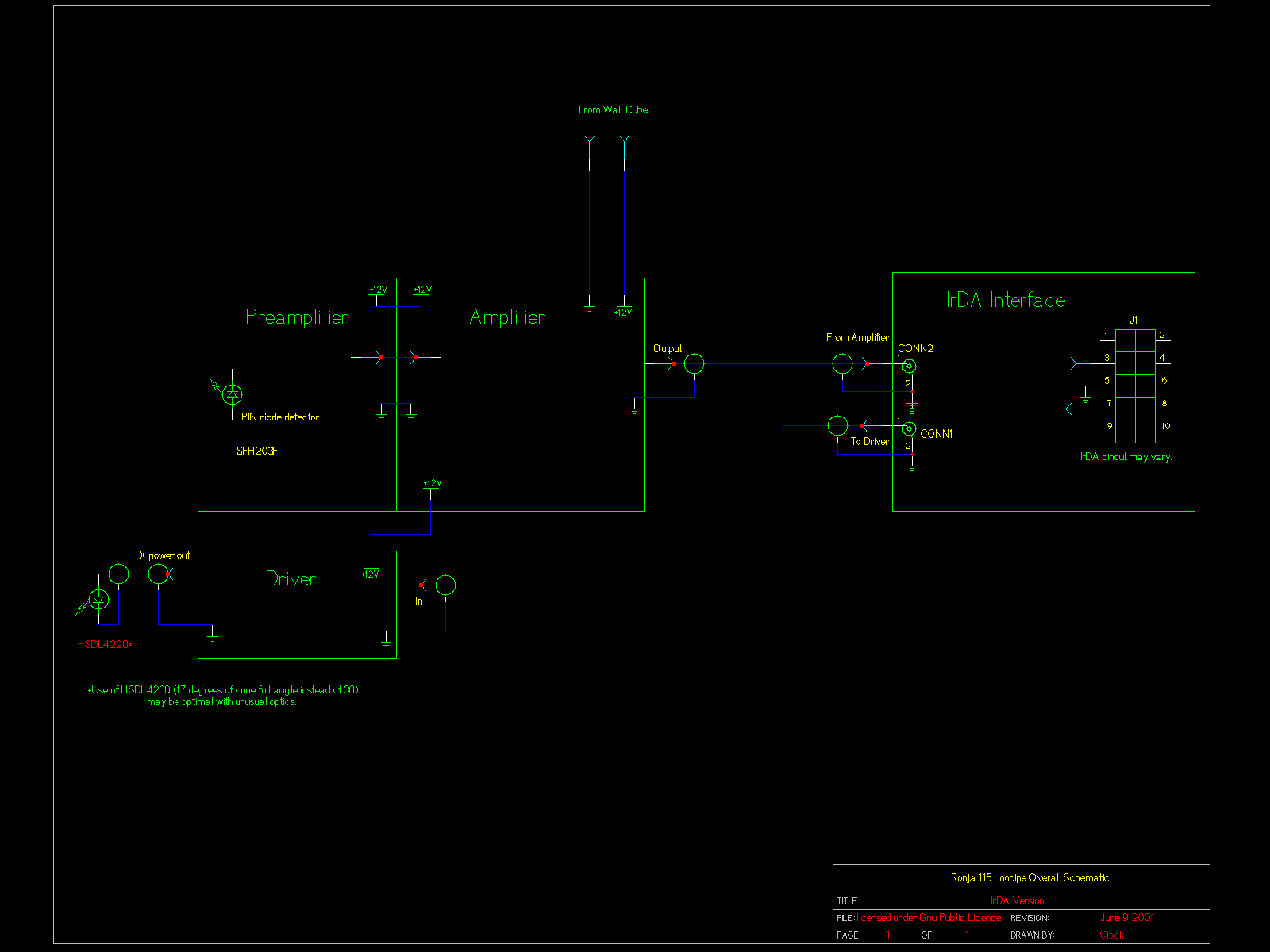
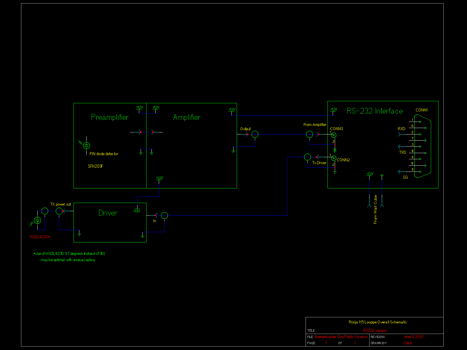
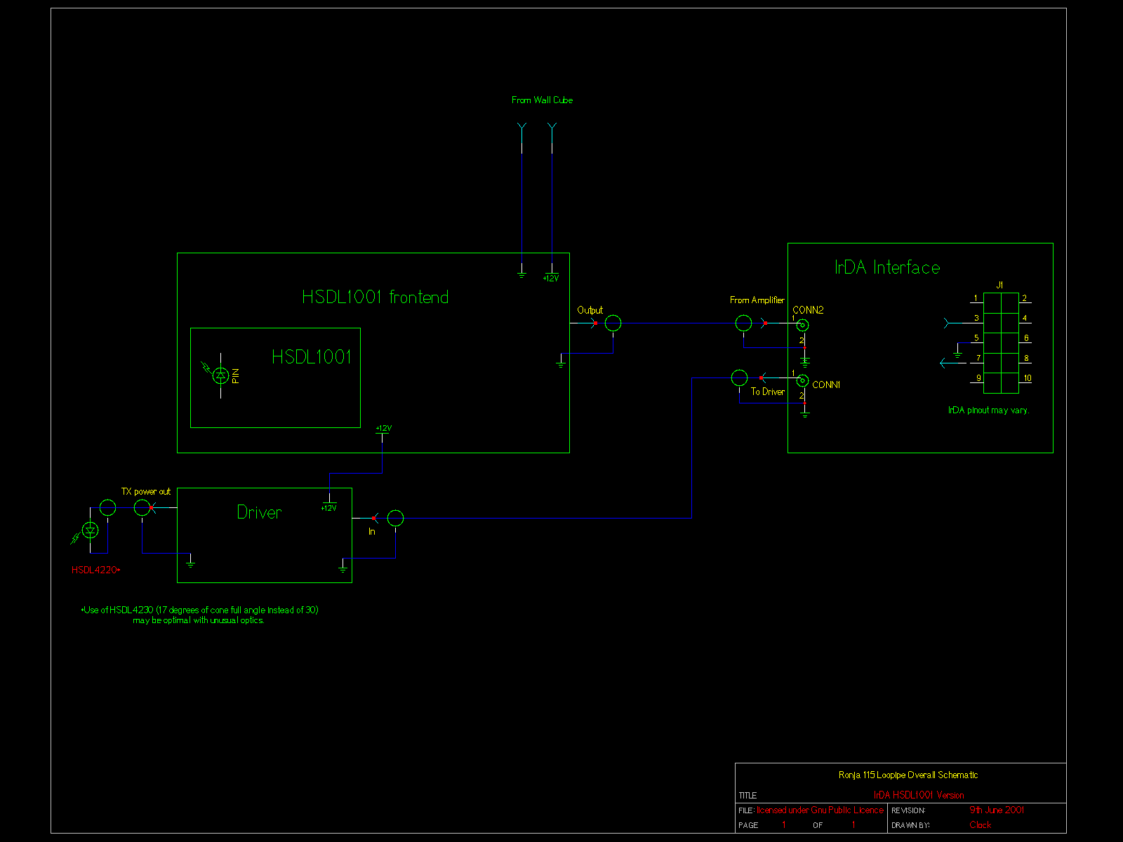
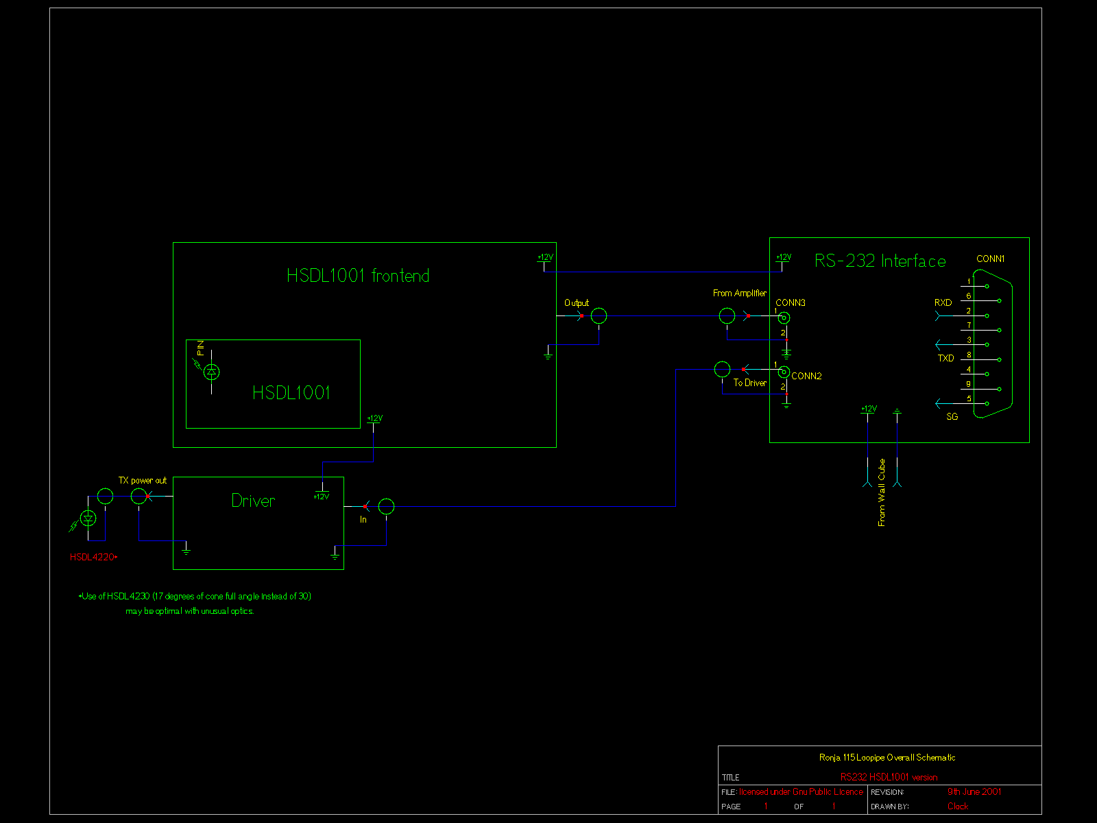
Overall schematic discusses how to interconnect the various Ronja Loopipe modules together to get a functional full duplex end of the optical route. There are several models of Ronja, differing in used modules. You select the modules for example according to the PC interface you wish (RS232 or IrDA SIR). You may place different versions on each end of the optical line. All version share common optical protocol.
The Ronja Loopipe modules are the following (with short characterization):
The indivindual versions that you may build are the following:
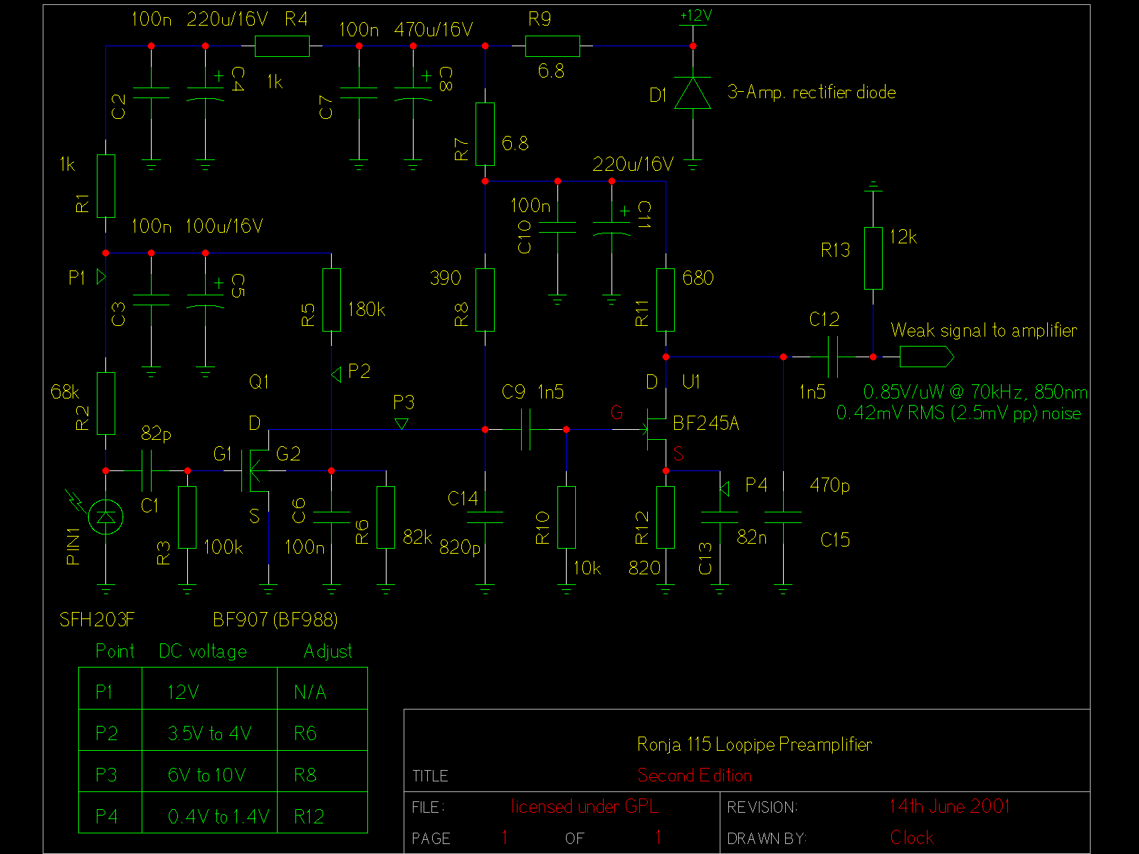
PNG and gschem schematic.
Here you have the part list:
| Resistors | |
| R1, R4 | 1k |
| R2 | 68k |
| R3 | 100k |
| R5 | 180k |
| R6 | 82k |
| R7, R9 | 6.8 |
| R8 | 390 |
| R10 | 10k |
| R11 | 680 |
| R12 | 820 |
| R13 | 12k |
| Capacitors | |
| C1 | 82p |
| C2, C3, C6, C7, C10 | 100n |
| C4, C11 | 220u/16V |
| C5 | 100u/16V |
| C8 | 470u/16V |
| C9, C12 | 1n5 |
| C13 | 82n |
| C14 | 820p |
| C15 | 470p |
| Semiconductors | |
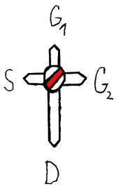
| Q1 | BF 907 or BF 988 or BF 998 |
| U1 | BF 245A |
| D1 | 3-Amp. rectifier diode |
| PIN1 | SFH203F |
| Hardware | |
| N/A | small metal shielding case |
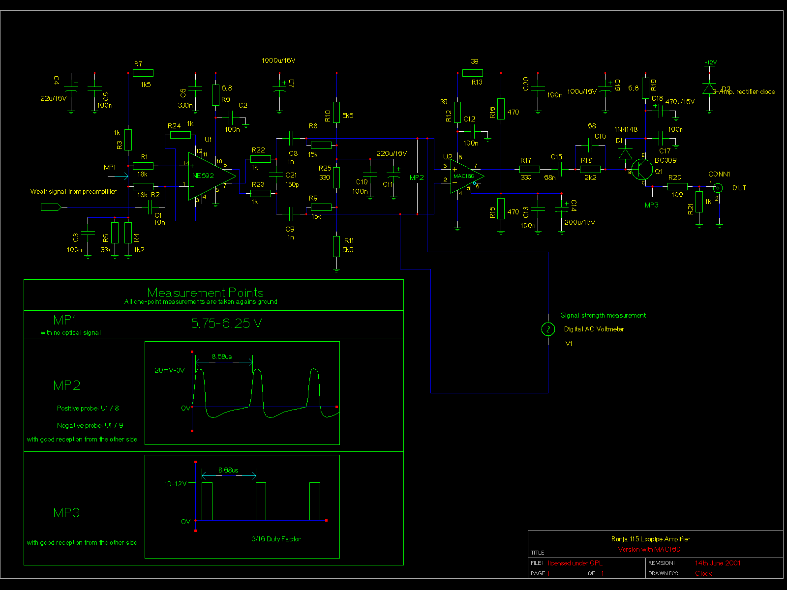
PNG and gschem schematic.
Here you have the part list:
| Resistors | |
| R1, R2 | 18k |
| R3, R21, R22, R23, R24 | 1k |
| R4 | 1k2 |
| R5 | 33k |
| R6, R19 | 6.8 |
| R7 | 270 |
| R8, R9 | 15k |
| R10, R11 | 5k6 |
| R12, R13 | 39 |
| R17 | 330 |
| R18 | 1k5 |
| R15, R16 | 470 |
| R20 | 100 |
| Capacitors | |
| C1 | 10n |
| C2, C3, C5, C10, C12, C13, C17 | 100n |
| C4 | 22u/16V |
| C6 | 330n |
| C7 | 1000u/16V |
| C8, C9 | 1n |
| C11 | 220u/16V |
| C14 | 200u/16V |
| C15 | 68n |
| C16 | 68p |
| C18 | 470u/16V |
| C19 | 100u/16V |
| C21 | 150p |
| Semiconductiors | |
| U1 | NE592 DIL-14 version |
| U2 | MAC 160 |
| D1 | 1N4148 (or any other medium-fast common Si diode) |
| D2 | 3-Amp. rectifier diode |
| Q1 | BC309 |
| Hardware | |
| CONN1 | BNC through-hole female |
| N/A | Metallic shielding enclosure |
Use R24 to set up NE592's gain so that the AC voltmeter shows about 100mV when sending a repeating pattern consisting of 70 consecutive chars "space" and 70 consecutive chars "lowercase o". Then possibly adjust R7 if data are corrupted (and the corruption is not caused by weak signal).
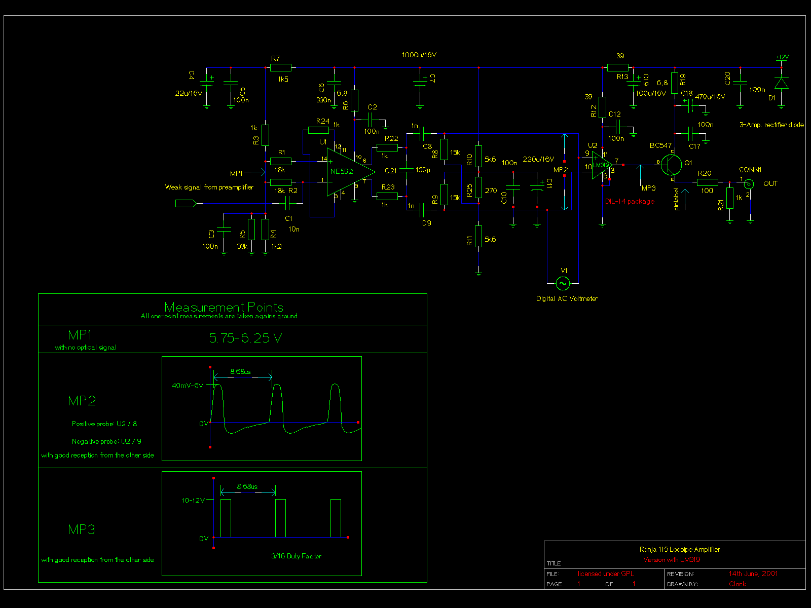
PNG and gschem schematic.
Here you have the part list:
| Resistors | |
| R1, R2 | 18k |
| R3, R21, R22, R23, R24 | 1k |
| R4 | 1k2 |
| R5 | 33k |
| R6, R19 | 6.8 |
| R7 | 1k5 |
| R8, R9 | 15k |
| R10, R11 | 5k6 |
| R12, R13 | 39 |
| R20 | 100 |
| R25 | 270 |
| Capacitors | |
| C1 | 10n |
| C2, C3, C5, C10, C12, C17, C20 | 100n |
| C4 | 22u/16V |
| C6 | 330n |
| C7 | 1000u/16V |
| C8, C9 | 1n |
| C11 | 220u/16V |
| C18 | 470u/16V |
| C19 | 100u/16V |
| C21 | 150p |
| Semiconductiors | |
| U1 | NE592 DIL-14 version |
| U2 | LM319 |
| Q1 | BC547 |
| Hardware | |
| CONN1 | BNC through-hole female |
| N/A | Metallic shielding enclosure |
Use R24 to set up NE592's gain so that the AC voltmeter shows about 100mV when sending a repeating pattern consisting of 70 consecutive chars "space" and 70 consecutive chars "lowercase o". Then possibly adjust R7 if data are corrupted (and the corruption is not caused by weak signal).
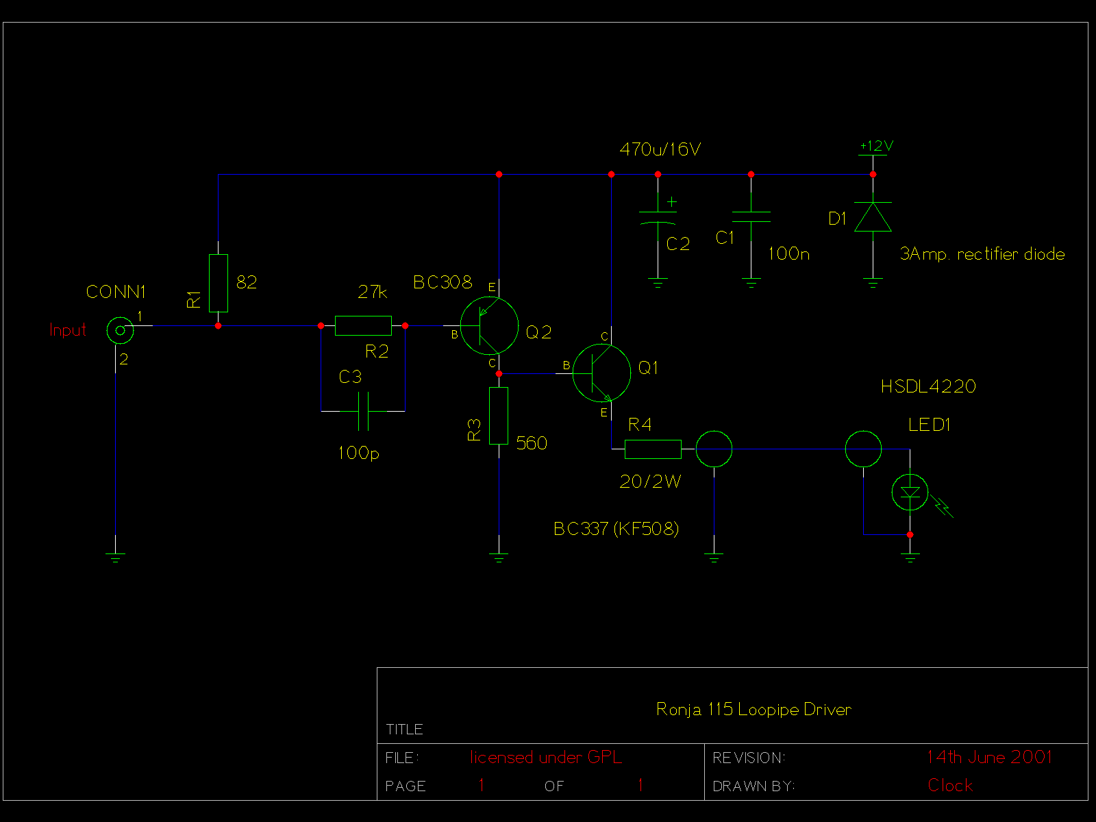
Driver is the piece driving the power LED: PNG and gschem schematic.
Here you have the part list:
| Resistors | |
| R1 | 82 |
| R2 | 27k |
| R3 | 560 |
| R4 | 20/2W |
| Capacitors | |
| C1 | 100n |
| C2 | 470u/16V |
| C3 | 100p |
| Semiconductors | |
| Q1 | BC337 (KF508) |
| Q2 | BC308 |
| D1 | 3Amp. rectifier diode |
| LED1 | HSDL4220 (maybe HSDL4230 for atypical optics) |
| Hardware | |
| CONN1 | BNC through-hole female |
| N/A | small metal shielding case |
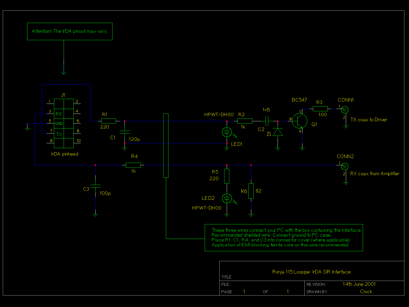
This interface connects to any IrDA pinhead on a motherboard. PNG and gschem schematic.
Here you have the part list:
| Resistors | |
| R1, R5 | 220 |
| R2, R4 | 1k |
| R3 | 100 |
| R6 | 82 |
| Capacitors | |
| C1 | 120p |
| C2 | 1n5 |
| C3 | 100p |
| Semiconductors | |
| Q1 | BC547 |
| D1 | 1N4148 (or any other medium-fast common Si diode) |
| LED1, LED 2 | HPWT-DH00 (or any other high-output LED) |
| Hardware | |
| CONN1, CONN2 | BNC through-hole female |
| J1 | 10-pin pinhead female |
| N/A | medium-sized metal shielding case or suitable plastic case |
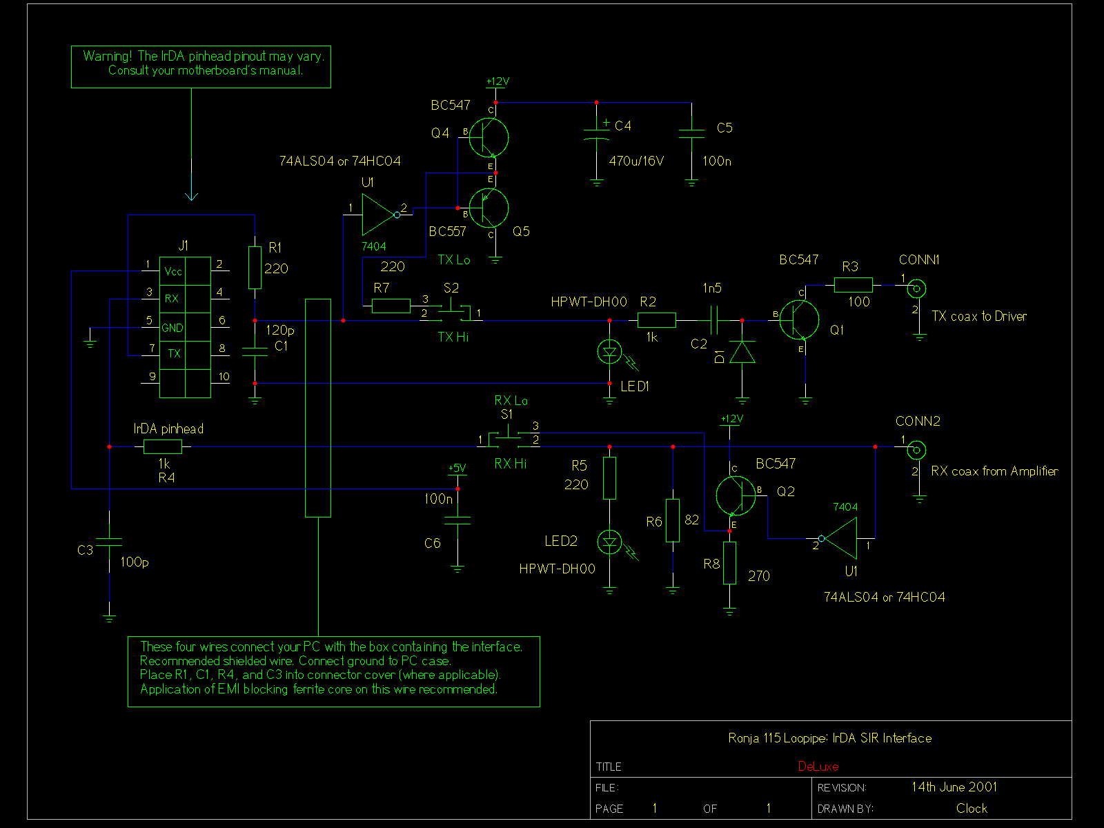
PNG and gschem schematic.
| Resistors | |
| R1, R5, R7 | 220 |
| R2, R4 | 1k |
| R3 | 100 |
| R6 | 82 |
| R8 | 270 |
| Capacitors | |
| C1 | 120p |
| C2 | 1n5 |
| C3 | 100p |
| C4 | 470u/16V |
| C5,C6 | 100n |
| Semiconductors | |
| D1 | 1N4148 or any other medium-fast silicon diode |
| LED1, LED2 | HPWT-DH00 or any other high-brightness visible LED |
| Q1, Q2, Q4 | BC547 |
| Q5 | BC547 |
| U1 | 74ALS04 or 74HC04 |
| Mechanics | |
| J1 | 10-pin 2x5 pinhead |
| CONN1, CONN2 | BNC thru-hole female |
| S1, S2 | 2-position switch |
| N/A | large metal shielding case |
| N/A | 1m of shielded 4-wire |
| N/A | ferrite blocking bead |
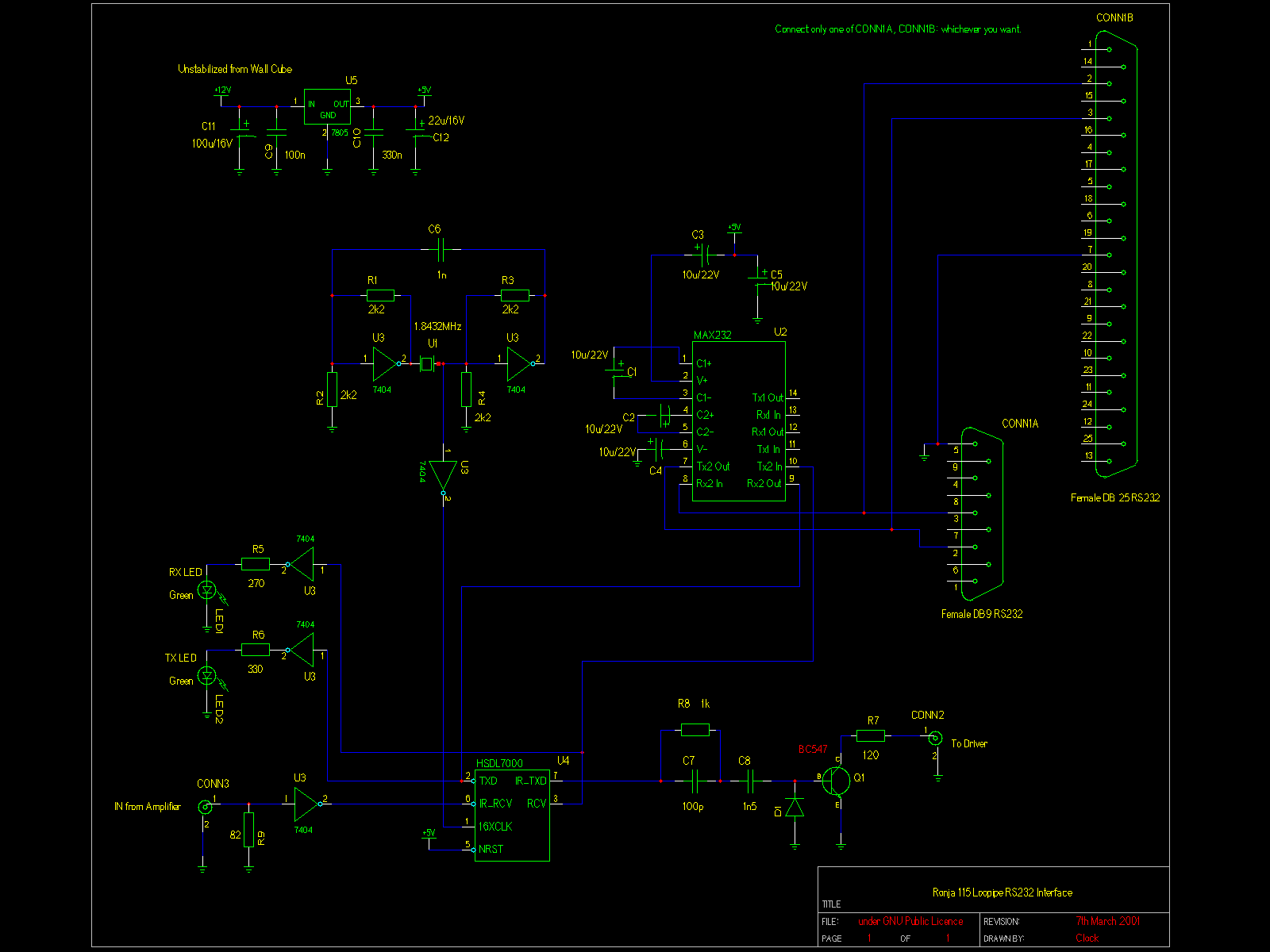
This connects to RS-232 (serial, asynchronous) port of your PC. The connector is specified for 9-pin Canon, but you can easily adapt it for 25-pin RS-232 Canon connector.
PNG, gschem schematic, obsolete PNG.
Here you have the part list:
| Resistors | |
| R1, R2, R3, R4 | 2k2 |
| R5 | 270 |
| R6 | 330 |
| R7 | 120 |
| R8 | 1k |
| R9 | 82 |
| Capacitors | |
| C1, C2, C3, C4, C5 | 10u/22V (100n for MAX 232A) |
| C6 | 1n |
| C7 | 100p |
| C8 | 1n5 |
| C9 | 100n |
| C10 | 330n |
| C11 | 100u/16V |
| C12 | 22u/16V |
| Crystal | |
| U1 | 1.8432MHz |
| Semiconductors | |
| Q1 | BC 547 |
| U2 | MAX232 (or MAX232A, then change C1 to C5) |
| U3 | 74ALS04 or 74LS04 or 74HCT04 |
| U4 | HSDL7000 |
| U5 | 78L05 or 7805 |
| Hardware | |
| CONN1 | DB9 female or DB25 female, whichever suits your PC port |
| CONN2, CONN3 | BNC female through-hole |
| N/A | large tin shielding case or suitable plastic case |
Attention. It is possible the crystal (1.8432 MHz) oscillator will have problems starting up. Use Pavouk's version instead in such case! However there has been a report Pavouk's oscillator had also problems starting up. Check if oscillator works when you try to debug the running device. How to check for running XTAL oscillator? Shine with a TV remote control and the RX led should blink. If the led stays in the same state (shining or dark), the oscillator is either bad or the amplifier or preamplifier or front end is not working properly. Sometimes I'll try to kick the sucking HSDL7000 and XTAL off and replace it with a pulse stretcher (monostable multivibrator).
The new version (drawn in gschem) contains capacitor that prevents DC overload of the transmitter in case of crystal clock failure.
If you have a 1.8432MHz ready oscillator in a small tin box, you can throw out the 3-gate oscillator on the schematics and use the ready-made. You can take the 5V from game connector of keyboard connector of your PC if you want. But do not short-circuit the 5V inside your PC when PC is running. The power consumption is small. You can use several equivalents of MAX232, the capacitor values can be adjusted for them. You must setup your port for 115200bps. The parity, data and stop bit setting is not important, but I recommend using 8bits, 1 stop bit, no parity.
The 1.8432 MHz doesn't need to be synchronous with that inside your PC. It works according to the HSDL7000 specs. If you can lead out the 16XCLK from your RS232 UART, you need no clocking circuit and simply use it instead of the oscillator.
It's a RS 232 HSDL1001 version.
There are seven infrared transmitter LED's on the LED board (HSDL4220 type). This is good for testing without optics, but for mounting into lens tube, you will need only one. Simply remove six of them together with their resistors (20 ohm).