The Time Energy Pump project
created on 09/19/97 - JLN Labs - last update on 09/19/97
NON-LINEAR TIME FLOW
JL Naudin comments :
The main goal of these tests is to understand the role of the ferrite rod inside a Non Inductive bifilar coils.
Look at the diagram in the attached document,
I have added a diode D5 and a 100 ohms resistor across the coil L1.
Scope probes are connected for measuring the voltage signal across R5 and R3 in SAME TIME.
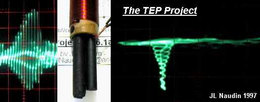
You have in the right side of the diagram three scope pictures with the associated position of the ferrite rod inside the NI bifilar. The scope pictures shows two signal from channel A and B centered on the zero volt line.
The interesting effect that I have noticed is the direct link with the rod position and the amplitude of the BackEmf voltage of each coil.
I can't explain clearly this effect, because the bifilar coil is an NON INDUCTIVE COIL ( in appearance.... ). And the coil is have BIFILAR winding, thus the signal induced must have a perfect symetry. This effect can be explained by the time stream propagation ( or the energy flow ) inside the bifilar coils.....The non linearity added by the ferrite rod may change the time flow when the magnetic energy arise and collapse in the coils.
See also : TEP V6.1a6 - The duty cycle tests