The "Magnetic paradox" explained
by Cyril Smith
created on 02/02/98 - JLN Labs - last update on 09/01/98
1. Introduction
Jean-Louis Naudin has drawn attention to a circuit which behaves in an unusual way in that the potential difference measured across two terminals can have different values according to which direction the connecting wires are taken. This paper presents an analysis of the system to explain this apparent paradox.
2. Discussion
The circuit involves electromagnetic induction and makes a good tutorial in highlighting some of the lesser known aspects. Most engineers are familiar with the voltage induced in a closed circuit by a time varying magnetic field which in its simplest form may be expressed as
![]() (1)
(1)
where F is the magnetic flux passing through the circuit. What many are not taught is that what causes this potential, the actual driving force F on the free electrons in the conductor, is not magnetic, but is Coulomb’s familiar electric force law
![]() (2)
(2)
where E is an electric field and e is the electron charge. The more fundamental version of equation (1) is
![]() (3)
(3)
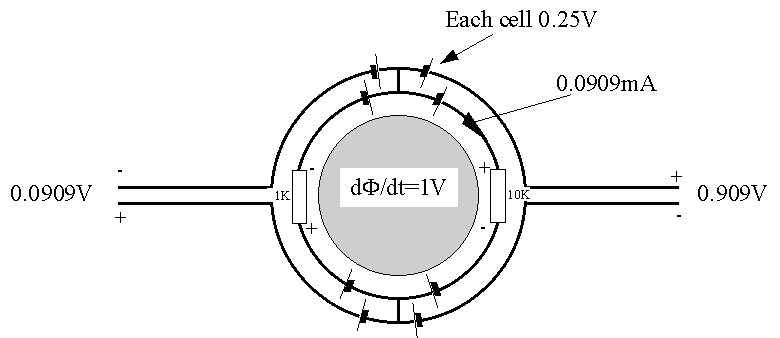
Around the changing magnetic flux is an E field which forms closed circles. The line integral (3) taken around one orbit is the familiar "volts per turn" of equation (1). What the magnetic paradox experiment demonstrates is that equation (3) applies even to non closed paths, or partial turns.
3. Solution
The experiment is shown in the following figure. Here for simplicity we have assumed that the changing magnetic flux gives 1 volt per turn. The circuit containing the resistors forms a complete turn around the magnetic field, so the induced voltage drives 0.0909mA through the 11KW load. The potential drop across the 1KW is 0.0909V and across the 10KW is 0.909V. Now the 1V induction actually occurs evenly spread along the length of the closed path, but for simplicity we show it occurring in the four quadrants as 0.25V per equivalent voltage generator. And since the take off wires also follow the quadrant paths we must also show the voltage induced in these. It is now a simple task to follow any path through the circuit from one volt meter terminal to the other, and to sum all the potentials en route including the potential drops across the resistors. We then find that one volt meter reads 0.0909V and the other 0.909V. Note that the polarity (phase) of the two outputs is also established.
Cyrillic Smith
2nd February 1998

![]() Email : JNaudin509@aol.com
Email : JNaudin509@aol.com
Return to the Quantum Electrodynamics page