The
Ion Wind Tests on Transdimensional's Lifter
By Jean-Louis
Naudin
created on October
10th, 2001 - JLN Labs - Last
update October 25th, 2001
All informations in this page are published free and
are intended for private/educational purposes and not for
commercial applications
In the Birmingham Business Journal ( July 19, 2001 ) we can read : " The scientific community has also mistaken Power3 for ion wind propulsion, although Transdimensional says ion wind contributes less than 2 percent of the system's total motive force. "
So, I have conducted two tests to check if the fact of removing the ion wind is able to cancel the upward thrust.
Ion Wind Test #1 :
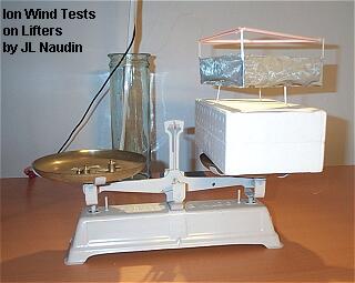
The Lifter1 that previously tested on Oct 1, 2001, has been used for these tests. The three thin copper wires has been completly insulated with Three 5 mm diam plastic tubes so as to remove the ion wind previously generated by these thin wires.


With these plastic tube the Lifter1 is not able to self-levitate, so it has been placed on a Roberval balance and insultated with a polystyren box.

TEST RESULT : When the High Voltage power supply is switched ON ( 41.9 KV @ 90uA - 37.7 Watts ), the Lifter1 goes upward and the needle of beam balance move to the left. ( see the photo and the video of the test below )

To see the videos, the free
downloadable RealPlayer is required ![]()
The Ion Wind Test #1

Click on the picture above to see the video ( 533 Kb )
Ion Wind Test #2 :
To check again if the main
lifting thrust is not generated by the ion wind. I have used a
thick cardboard sheet between one wire and the main armature. In
the case of the ion wind generates all the thrust, when a
cardboard shield is placed below one of the wires, the Lifter
must tilt on one side due to the resulting asymmetrical flow.
A such test has also been performed by Transdimensionnal
Technologies ( see : http://www.tdimension.com/video_pages/lifter_ion.htm )
TEST RESULT : When the High Voltage power supply is switched ON, the device remains stable and continue to hovering at the same level. ( see the photos and the videos below )

The Ion Wind Test #2

Click on the picture above to see the video ( 978 Kb )
Air Bag Test #3 :
The Lifter has been completly enclosed with a plastic bag and placed on a Robeval balance.

TEST RESULT : When the High Voltage power supply is switched ON, the Lifter goes upward with the plastic bag and the needle of beam balance move to the right. ( see the photo and the video of the test below )

The Plastic Bag Test #3

Click on the picture above to see the video ( 506 Kb )
Ion wind speed measurements : Test #4
The purpose of this test is to measure the ion wind generated below the surface of Lifter. I have used Huger Wind speed meter WSC100H. This windmeter has a measuring range for wind speed: 0 to 220 km/h, 0 to 115 knots, 0 to 60 m/s, 0 to 125 miles/h with an accuracy of +/- 3% from -30° to 70° C.

According to a calculation done by William Beaty :
Regarding the controversy of ion wind thrust versus
electrogravity, just how much wind would be needed to
levitate the Lifter? then: engine thrust = (air vel)^2 * area of
jet * exhaust density (snip).... (((((((((((((((( ( ( ( (
(O) ) ) ) )
))))))))))))))))))) |
|||||||||||
TEST RESULT : The Wind Speed meter is placed below the surface of the Lifter and moved along the entire of the this area, the average ion wind speed measured is about 1.5 mph ( 0.67 Meter/sec ). The ion wind contribution to the upward thrust is more than the 2% claimed by Transdimensional Technologies, but it is not sufficiency to lift the device.

The Ion Wind measurements Test #4

Click on the picture above to see the video ( 569 Kb )
| Even if, in the worst case, a fluid medium is required to lift off, the Lifter technology is a good starting point for building highly manoeuvrable VTOL crafts which will flight silently without moving parts... Jean-Louis Naudin - April 30, 2002 |
![]() Lifter theory
proposal by
Evgenij Barsoukov
Lifter theory
proposal by
Evgenij Barsoukov
![]() Towards a
thrust/power ratio up to 40g/W
by Evgenij Barsoukov
Towards a
thrust/power ratio up to 40g/W
by Evgenij Barsoukov
![]() Read the NASA Patent
description and see
the FULL
NASA PATENT US 6,317,310 ( granted November 13, 2001 )
Read the NASA Patent
description and see
the FULL
NASA PATENT US 6,317,310 ( granted November 13, 2001 )
NASA MFS 31419_1 -
Apparatus & Method for Generating Thrust Using a Two
Dimensional, Asymmetrical Capacitor; - see the photo of the apparatus tested in vacuum by TdT
Electrokinetic Propulsion: The Ionic Wind Argument by William B. Stein - Purdue University - Energy Conversion Lab
 A
Proposed Electrodynamic Thrusting Mechanism
by Charles A. Yost
A
Proposed Electrodynamic Thrusting Mechanism
by Charles A. Yost
![]() Email : JNaudin509@aol.com
Email : JNaudin509@aol.com
Return to the Lifters experiments page