
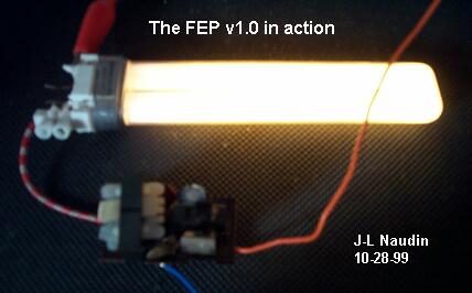
The Free Electrons Pump ( FEP v1.0)
By Stefan Hartmann and Jean-Louis Naudin
created on October 28th, 1999 - JLN Labs - Last update November 6th, 1999
This device is based on the Stefan Hartmann's experiment released on October 26th, 1999 : "The Electron Pumping FL tube light".

Now, I have reproduced and tested successfully the Hartmann's basic device and improved the design, so I have built the Free Electrons Pump v1.0 :
The FEP v1.0 is an enhanced version which uses a spherical capacitor coupled with the earth atmosphere. As Nikola Tesla had used in the Power Wave experiment in Colorado springs in June 26, 1899 and also during his tests of the first models of the Tesla Magnifier Amplifier tower, the FEP v1.0 uses the same principle for sucking free electrons from the atmosphere : " To produce an electrical movement of the required magnitude it is desirable to charge the terminal as highly as possible, for while a great quantity of electricity may also be displaced by a large capacity charged to low pressure, there are disavantages met with in many cases when the former is made too large. The chief of theses are due to the fact that an increase of the capacity entails a lowering of the frequency impulses or discharges and diminution of energy of vibration....." ( Tesla US Patent number 1,119,736 : "Apparatus for transmitting electrical energy" (issued Dec. 1, 1914) ).

The FEP v1.0 uses a spherical capacitor made with an aluminum hollow sphere ( 365 mm diam. and 240 mm height ). A 9 Watt neon tube (OSRAM 9W/Dulux S 41/82) is connected between the FEP generator and the aluminum sphere.

The FEP generator is a High Voltage Pulses generator which produces 1380 V pulses at about 29 kHz (see below). The FEP transformer (L1,L2,L3) is a high frequency transformer (with ferrite core) which can be found in common portable neon lights (used for camping). But you can also use L1 (7 turns of 4/10mm), L2 ( 6 turns of 5/10 ), L3 ( 750 turns of 1/10 ) wound on a ferrite core 10mm diam. If you find a ready made ferrite HF transformer, this will be better.


The 9W neon tube is a common low consumption light tube, but I have removed its original starter circuit.


The FEP Generator MUST BE powered by a battery source ( I have used a 12V 4 Ah lead acid battery) and MUST NOT BE GROUNDED. This is very important, because the system MUST BE OPEN. If you ground the FEP generator circuit, you build a common closed system and free electrons can't be tapped.
TESTING RESULTS (10-28-99)
I have used an analog voltmeter and an analog ammeter, this is strongly recommended for avoiding some parasitic effects due to the electromagnetic waves induction (EMI) in some digital equipments which can generate some "false/true" measurements....
So, when the power is switched on WITHOUT the neon tube ( with the FEP output left opened ), the power input required for the functionning of the FEP circuit is 5.17 Watt (11.5 Volt and 450 mA DC input )(see below).

When the 9W neon tube is connected with its spherical capacitor, the power input DROPS to 4.66 Watt (11.5 Volt and 405 mA DC input ) while the neon tube throws out about 30% of its max light...(see below)

Note : If you don't have an aluminum spherical capacitor, you may also use a big aluminum sheet as a free electrons collector.
Now that you have a very simple electronic circuit that you can build and test by yourself, you will notice that this circuit works very well and shows that some free electrons can be tapped easily, from the atmosphere or from the ground with the FEP v1.0 device...
Jean-Louis Naudin October 28th, 1999
POWER I/O Measurements ( JLN 10-29-99) :
The 9 Watt neon tube has been replaced by a 15 Kohm-5 Watt ( the exact value was 16340 ohm) carbon resistor (see below) :

I have used a Textronix THS720P isolated and ungrounded channels oscilloscope for measuring the voltage accross the output resistor. The RMS and PEAK output voltages has been computerized automaticaly by the scope.

JLN Comments:
As you may notice in the diagram above, the measured output power accross the resistor was 801 mW RMS for 8.6 Watt Peak, the most interesting thing to observe is that THE INPUT POWER DROPS of 226 mW while 801 mW is generated at the output.
See also :
A successful replication of the FEP v1.0 device by David Mason ( 04-25-00 )
The new FEP v2.0 generator
The AFEP v1.0 ( The Avramenko's Free Electrons Pump device )
Reference documents :
1) "The Electrical Experimenter: My
Invention by Nikola Tesla", June 1919
2) Tesla: Man Out of Time, by Margaret Cheney - Prentice-Hall,
Inc
3) Tesla US Patent number 1,119,736 : "Apparatus for
transmitting electrical energy" (issued Dec. 1, 1914)
4) Tesla US Patent number 8,200 : " Improvements relating to
the transmission of Electrical Energy" (17th Apr.,1906)
5) Theory of Wireless Power, By Eric Dollard, B.S.R.A. 1986.
6) "Tesla's Tower (Wardenclyffe) by ESJ Staff - Electric
Spacecraft Journal, issue 2 (1991)
7) "The Power Wave (1899-1991)" by Ron Kovac - Electric
Spacecraft Journal, issue 3 (1991)
![]() Email : JNaudin509@aol.com
Email : JNaudin509@aol.com
or send email to the JLN Lab's eGroup at : jlnlabs@egroups.com if you are a team member.
Return to Tesla Exploration home page