Bifilar Coils Testing
The Time Energy Pump project
created on 08/24/97 - JLN Labs - last update on 08/24/97
I have conducted some tests to understand better the working process in the TEP.
The main goal of these series of tests is to understand better how a Bifilar
coil works.

I have used :

- a BIFILAR coil L1,L2 ( interweaved ) which has a calculated inductance
  of 0.59 mH ( each )

The tested coils are switched through a transistor BDX53C by a square wave
generator..
The signal is sent through a coil L3 ( wounded around the bifilar ).
Calculated inductance : L3 = 7.6 mH
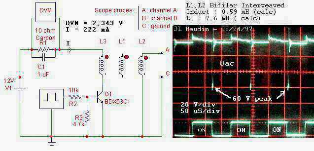
Case 1 :The Bifilar properties is not used, the square signal is sent on L3 coil and received on L2 ( one coil of the bifilar ).
You will see a normal induction setup during the ON/OFF sequences with a 60 V peak signal induced on L3.
The DVM ( Digital VoltMeter ) indicates I=222 mA and V=2.343 Volts across a (10ohm + 1uF )
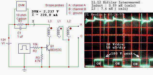
Case 2 : The HOT side of the coil L1 of the bifilar is connected to the COLD side of the coil L2 of the bifilar, thus the COLD side of the coil L1 of the bifilar remains open.
You will see a normal induction setup during the ON/OFF sequences BUT with a 100 V peak signal induced on L3.
The DVM ( Digital Voltmeter ) indicates
I=220.8 mA and V=2.237 V across a (10ohm + 1uF )
Case 3 : The
COLD side of the coil L1 of the bifilar is connected to the HOT side
of the coil L2 of the bifilar, thus the HOT side of the coil L1 of
the bifilar remains open.
You will see NO EFFECT on the Current and
Voltage on the DVM, it remains constant as in Case 1
NOTES : If you connect a LED (with a 47 K
resistor in serial ), you will see that the light of the LED will be
more bright in the Case 2 than in the Case 1.
But the current in the circuit
always DROPS in
the Case 2.....